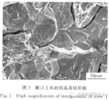
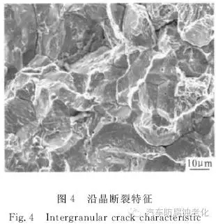
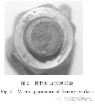
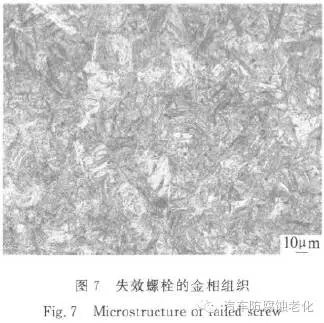
Discuss the main factors affecting the hydrogen embrittlement sensitivity of steel fasteners. According to the analysis, the influence of material strength on hydrogen embrittlement sensitivity should be fully considered in design, and the strength level should be reduced as much as possible. The appropriate heat treatment process should be adopted to reduce the intercalation elements in the grain boundary and inhibit the formation of film-like carbides, thus obtaining hydrogen. Microstructure with small brittle sensitivity; in the process of processing and assembly, mechanical damage should be avoided on the surface of the part as much as possible; low hydrogen embrittlement plating process should be adopted, and if necessary, a coating method such as Dacromet without hydrogen embrittlement should be adopted; After electroplating, a reasonable hydrogen removal process is adopted to carry out strict hydrogen removal treatment; for reusable parts, after the acid removal and removal of the plating layer, the hydrogen removal treatment is performed first, followed by electroplating, and then hydrogen removal. Since the discovery of hydrogen embrittlement in the 1940s, it has been a major problem that seriously threatens the safety of product use. Since the parts have no signs before the occurrence of hydrogen embrittlement fracture and have the characteristics of delayed damage, it is impossible to find out whether the bolts will undergo hydrogen embrittlement fracture through normal inspection procedures. Therefore, once the parts are subjected to hydrogen embrittlement fracture, they often have very serious consequences. In recent years, advanced weapons and equipment have become more and more demanding on the strength of materials, especially steel materials, and a large number of high-strength steels have been adopted. As the strength of steel parts increases, the sensitivity to hydrogen embrittlement increases, resulting in the hydrogen brittle fracture of high-strength steel components. The frequency of occurrence in the defense industry such as aviation and aerospace is getting higher and higher. The use of this brings a great security risk. Steel fasteners have been widely used in the military industry due to their high strength and low material cost. Although the fasteners are small but large in quantity, they are mostly connected to the bearing members. Once they fail, they may cause serious accidents. Hydrogen embrittlement fracture of steel fasteners under static tensile load is a common failure mode. Because hydrogen embrittlement is mostly related to “batch†problem, it is more harmful. For a long time, the mechanism of hydrogen embrittlement fracture has been a hot topic of research, but these research results are difficult to directly apply to the failure prevention of practical engineering components. The hydrogen embrittlement problem of steel fasteners, especially high-strength steel fasteners, is still very prominent. This work explores the factors affecting hydrogen embrittlement fracture from the aspects of design, manufacturing (heat treatment, machining, electroplating, hydrogen removal, etc.) by introducing the hydrogen embrittlement failure cases of typical steel fasteners. Practical measures to prevent hydrogen embrittlement failure of steel fasteners. 1 typical case analysis 1.1 Case 1: Hydrogen embrittlement fracture of engine nozzle screw The hydraulic blasting experiment of a solid rocket motor combustor shell is carried out. When the pressure is up to 11.8 MPa (the design requires the blasting failure pressure to be not less than 24.1 MPa), the test is blocked at the rear end of the combustion chamber shell and the pressure is released. The heads of the third, fourth, and fifth nozzle fixing screws from the second quadrant to the third quadrant are broken and fly out. The screw material is 30CrMnSiNi2A ultra high strength steel. The screws are all broken at the first thread. The macroscopic features of the fracture are basically the same, dark gray, the fracture is flush, and the section shows the radiation ridge. The ridge line shows that the fracture originates linearly from the relief groove, as shown in Figure 1. There are two distinct areas on the fracture: zone I is crystalline and granular, and zone II is fibrous. The work area (source area) has a microscopic appearance along the crystal shape, and the grain outline is clear. The crystal interface is covered with a thin strip of tearing ridge line, which can be seen as a “chicken-like†morphology and a secondary crack, as shown in Fig. 2. Zone II is characterized by dimple fracture. Material inspection showed that the microstructure of the screws was tempered martensite, lower bainite and a small amount of retained austenite, and the structure was normal. The hardness of the screws is about 49HRC, which is within the range of 48~50.3HRC required by the design; the tensile strength after conversion is about 1690MPa, which meets the design requirements of = 1666MPa±98MPa. The hydrogen content test results show that the hydrogen content of the screw matrix is ​​less than 0.0001%. The failure analysis results show that the fracture property of the screw is hydrogen embrittlement fracture. According to engineering experience, the hydrogen content of less than 0.0001% of the mass fraction does not easily lead to hydrogen-induced brittle fracture of the 30CrMnSiNi2A screw. The tensile strength of the screw hardness conversion is about 1690 MPa, which meets the design requirements of σb = 1666 MPa ± 98 MPa. However, the initial design strength of the screw material σb = 1500 MPa ± 98 MPa, according to the quenching + tempering heat treatment system, the tempering temperature should be around 360 ° C, just in the tempering brittle temperature range of the material (350 ~ 550C). In order to avoid temper brittleness, the design department changed the design strength to σb=1666MPa±98MPa, and adopted the heat treatment system: 90~910°C, oil quenching, 300C±30°C, tempering. After the heat treatment, the strength of the screw meets the design requirements, but hydrogen brittle fracture failure occurs during use. In order to find the real cause of the fracture, the design strength of the screw material is changed back to the initial value σb=1500MPa±98MPa. For this purpose, the austempering is used instead of the quenching+tempering process, that is, 890~910C heating, 310~330C for 1h, air cooling. After using this process, the strength of the material is in the range of σb = 1500 MPa ± 98 MPa. After the above improvement measures, the hydrogen embrittlement fracture of the screw is effectively prevented. It is shown that the fracture of the screw is mainly due to the high tensile strength of the screw material, which increases the hydrogen embrittlement sensitivity of the screw. 1.2 Case 2: 30CrMnSiNi2A bolt hydrogen embrittlement fracture The source area of ​​the bolt fracture is shown in Figure 3, which originates along the arc of the surface of the bolt. The fracture characteristics of the fracture along the crystal are shown in Fig. 4. The crystal interface is rough and covered with small strips of tearing ridges, and the "chicken-like" morphology and secondary cracks are partially visible. The bolt structure is normal, and the Rockwell hardness and tensile strength obtained by the microhardness test result meet the technical requirements. The mass fraction of the hydrogen content of the matrix was measured to be about 0.0004%. Engineering experience shows that the hydrogen content is sufficient to cause hydrogen embrittlement fracture of 30CrMnSiNi2A steel. Therefore, the bolt fracture is mainly related to the high hydrogen content. 1.3 Case 3: Engine inlet bolt breakage The right inlet bolt of an engine was flying for 5h25min, and it broke in the air after 6 flights. The bolt material is 30CrMnSiA. It is a reusable part. After the surface is electrically de-oiled and the old zinc layer is removed, the surface is electrogalvanized. After galvanizing, the hydrogen removal treatment is performed at 190 ° C ± 10 ° C / 4 h. The bolt breaks at the root of the first thread, the fracture is flat, black-gray, and the flashing facet features are visible locally, as shown in Figure 5. The edge of the fracture is mostly characterized by intergranular fracture, see Figure 6. Metallographic examination of the failed bolts and the intact bolts of the secondary galvanizing of the same batch of furnaces shows that the structure of the failed bolts is tempered martensite, and the structure of the intact bolts is tempered sorbite, see Figure 7 respectively. And Figure 8. Microhardness testing was performed on the failed bolts and the intact bolts of the same batch of secondary galvanizing, and converted into tensile strength. The results are shown in Table 1. It can be seen that the hardness and strength of the broken bolt are higher than the intact bolt, and the tensile strength is higher than the specified requirement (1080~1280 MPa). The test results of the hydrogen content of the bolts in the same batch are shown in Table 2. It can be seen that the hydrogen content in the bolts of the same batch is higher. 1.4 Case 4: Landing frame 300M steel screw makeup hydrogen embrittlement fracture After the screwing pile of an aircraft landing gear is installed for a period of time, the screw pile breaks and the fracture is located at the root of the first thread. The stud material is 300M steel and the surface is treated with cadmium-titanium plating. The tensile strength is 1892 MPa from the hardness of the tested screw pile, which meets the requirements of the technical specification σb = 1960 MPa ± 100 MPa. The hydrogen content of the failed studs, a mechanically damaged stud with the same batch of failed studs, the new non-mechanical studs and the raw materials were tested. The results are shown in Table 3. It can be seen that the hydrogen content of the failed component is higher than that of the non-mechanical damaged stud piled in the same batch as the failed stud pile, which is slightly higher than the hydrogen content of the raw material; and, in addition to the failed component, the same pile pile and the failed stud pile and The hydrogen content of the new screw piles is lower than that of the raw materials, which indicates that the high hydrogen content of the failed piles has nothing to do with the electroplating and dehydrogenation processes, but is directly related to mechanical damage. Therefore, surface mechanical damage is the main cause of hydrogen embrittlement fracture of studs. Fluorographene used as cathode material of
lithium batteries,These lithium primary batteries have the advantages
of high energy density, high discharge voltage, stable discharge curve,
wide operating temperature, extremely long shelf life, which has great
application potential in the aerospace and high-end civil field. Fluorographene Shandong Zhongshan Photoelectric Materials Co., Ltd , https://www.chzsem.com
A batch of 30CrMnSiNi2A bolts undergo a large number of cracking or fracture during use, and then measures such as improving the surface finish and the processing quality of the corner R at the root of the hexagon of the bolt, the bolt still breaks during use. 


The failure analysis results show that the hydrogen embrittlement fracture of the bolt is mainly related to the high strength of the bolt material and the high hydrogen content. 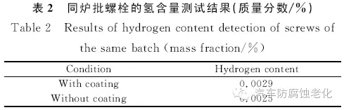
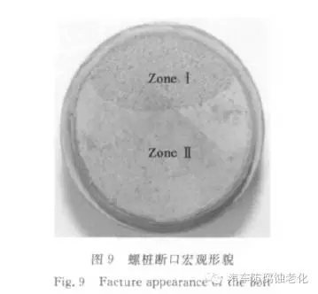
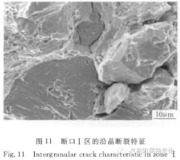
The macroscopic shape of the screw pile fracture is shown in Figure 9. It is divided into two areas: the section I is rough and dark gray, which is crystalline and granular, accounting for about 1/3 of the total area of ​​the fracture. The area II is flat and silvery, accounting for the total area of ​​the fracture. 2/3 or so. Obvious signs of mechanical damage can be seen at many points on the edge of the fracture, see Figure 10. The high-magnitude morphology of the I region is characterized by intergranular fracture, and the crystal interface is not smooth, but is covered with a thin strip of tearing ridges, and a "chicken-like" morphology can be seen locally, as shown in Fig. 11. Zone II is a momentary fault zone and is characterized by a dimple fracture. The energy component analysis was carried out from the edge to the inside of the fracture I region. No cadmium was found along the crystal region. It can be seen that the generation of the intergranular crack has nothing to do with cadmium brittleness. It can be seen from the microscopic characteristics of the screw pile fracture that the fracture property of the screw pile is hydrogen brittle fracture.