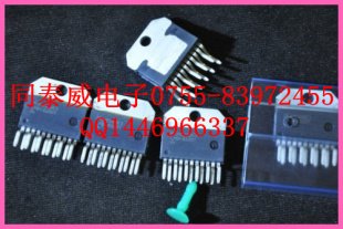
1, the main performance l Peak output current up to 6A, continuous output current up to 3A; 2, typical application l Drive DC motor, step motor 3, internal structure and pin description The outline structure of LMD18200 is shown in Figure 1. The internal circuit block diagram 2 is shown in the figure. It has 11 pins and is available in TO-220 and dual in-line packages. The function of each pin is as follows: Pin name Functional description 1 , 11 Bootstrap input capacitor connection of bridge arms 1 , 2 10uF bootstrap capacitor should be connected between pin 1 and foot 2 , foot 10 and foot 11 2 , 10 H- bridge output 3 Direction input When steering, the output drive current direction is shown in Table 1 . This pin controls the direction of the current between output 1 and output 2 (pins 2 , 10 ) to control the direction of motor rotation. 4 Brake input When braking, the output drive current direction is shown in Table 1 . The motor winding is short-circuited by this end to brake it. When braking, set the pin to a logic high level and set the PWM signal input (pin 5 ) to a logic high level. The logic state of pin 3 is determined by the device used to short the motor. When the pin 3 is logic high, H high bridge two transistor; pin 3 form a logic low level, H bridge two low-side transistor is turned on. When pin 4 is set to logic high and pin 5 is set to logic low, all transistors in the H- bridge are turned off. At this time, each output has only a small bias current ( 1.5 mA ). 5 PWM signal input The relationship between the PWM signal and the direction of the drive current is shown in Table 1 . How this end is used with the 3 pin (direction input) depends on the PWM signal type. 6 , 7 Positive and negative ends of the power supply 8 Current sampling output A current sampling signal is provided, typically 377 μA/A . 9 Temperature alarm output Temperature alarm output, providing temperature alarm signal. When the junction temperature of the chip reaches 145 °C, the terminal goes low; when the junction temperature reaches 170 °C, the chip turns off. Table 1 LMD18200 logical truth table  PWM Turn brake Actual output drive current Motor working state H H L Outflow 1 , inflow 2 Forward H L L Inflow 1 and outflow 2 Reverse L × L Outflow 1 , outflow 2 stop H H H Outflow 1 , outflow 2 stop H L H Inflow 1 , inflow 2 stop L X H NONE How the LMD18200 works : Four DMOS tubes are integrated inside to form a standard H-type drive axle. The gate control voltage is supplied to the two switching tubes of the upper arm through the charging pump circuit, and the charging pump circuit has an operating frequency of about 300 kHz. The second charging pump circuit can be formed on the external capacitors of pins 1 and 11. The larger the external capacitor is, the faster the charging speed of the capacitor input to the gate of the switching tube is, and the shorter the voltage rise time, the higher the operating frequency can be. Pins 2 and 10 are connected to the DC motor armature. The direction of current should be from pin step to pin 10 during forward rotation; the direction of current should be from pin 10 to pin 2 when reversed. The current detection output pin 8 can be connected to a ground resistor to output an overcurrent condition through the resistor. The overcurrent threshold set by the internal protection circuit is 10A. When this value is exceeded, the output is automatically blocked and the output is automatically restored periodically. If the overcurrent lasts longer, the overtemperature protection will turn off the entire output. The overheat signal can also be output on pin 9, which has an output signal when the junction temperature reaches 145 degrees. 4, typical application The typical application circuit of LMD18200 is shown in Figure 3. The LMD18200 offers bipolar drive and unipolar drive. Bipolar drive means that the polarity of the voltage of the motor armature changes positively and negatively during one PWM period. Although the bipolar reversible system has the advantages of low speed running stability, it also has the disadvantages of large current fluctuation and large power loss. In particular, the dead zone must be increased to avoid the danger of the switch tube being straight through, and the switching frequency is limited. Therefore, it is only used for the control of small and medium power DC motors. This article describes the unipolar reversible drive method. The unipolar driving method means that the motor armature is only subjected to a unipolar voltage during one PWM period. The application circuit is an example of the Motorola 68332CPU and LMD18200 interface, which form a closed-loop control circuit for a unipolar drive DC motor. In this circuit, the PWM control signal is input through pin 5, and the turn signal is input through pin 3. The speed and steering of the DC motor are determined according to the duty cycle of the PWM control signal. An incremental photoelectric encoder is used to feed back the actual position of the motor, output two phases of AB, detect the motor speed and position, and form a closed loop position feedback to achieve precise control of the motor. 5, the conclusion The digital control of the motor is the development trend of the motor control. Controlling the motor with the single-chip microcomputer is the most common means to realize the digital control of the motor. Using the special motor control chip LMD18200 can reduce the burden on the MCU and make the work more reliable.
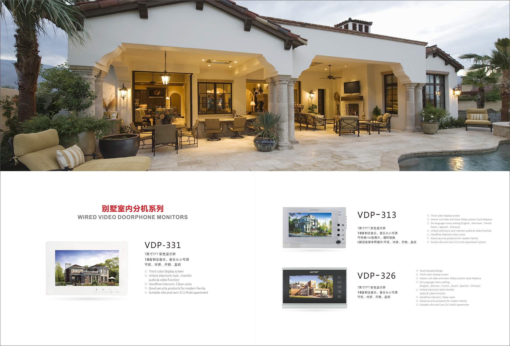
Memory Video Door Phone is a fashion Video Door Phone with indoor monitor and outdoor camera.
Outdoor camera is 0.3M pixel and night vision.
Indoor monitor is 7 inch color monitor with memory function. When have visitor press doorbell, can take a picture automatically, also support to take photo manually. It support to store 100 pcs pictures and cycle replace.
l Working voltage up to 55V;
l Low RDS(ON) typically 0.3W per switch;
l TTL/CMOS compatible level input;
l No "shoot-through" current;
l With temperature alarm and overheat and short circuit protection;
l The chip junction temperature is 145 ° C, the junction temperature reaches 170 ° C, the chip is turned off;
l Has good anti-interference.
l Servo system position and speed
l applied to the robot control system
l applied to digital control systems
l applied to computer printers and plotters
★☆★★☆★★☆★★☆★★☆★★☆★★☆★★☆★★☆★★☆★★☆★★☆★★☆★★
Optocoupler, Hall element, fast recovery, Schottky, high frequency tube, module, microcontroller, Darlington, capacitor resistors and various cold-gate electronic components. Products are widely used in civil, industrial, military and many other fields, products cover home appliances, networks,
Specific application products are: power amplifiers, speakers, energy-saving lamps, microwave ovens, induction cookers, water heaters, refrigerators, air conditioners, power supplies,
Wholesale and retail are welcome, the company undertakes large and small orders! 

Memory Video Door Phone
Memory Video Door Phone,Take Photo Video Door Phone,Photo Recording Video Door Phone,Video Door Phone With Memory
Shenzhen Zhuohao Intelligent Electronic Development Co., Ltd. , http://www.szactop-smart.com