Switch tube selection
The design switch tube adopts Mitsubishi high-speed IGBT module CT35SM-8. Previously used high-power IGBTs such as 2MBI200 have relatively large packages, which are not suitable for pulse power supplies used in machine tools. The advantages are small size, high pressure and current resistance. The CT35SM-8's VCES can reach 400V and the ICM can reach 200A. The current requirement of 0~200A can be achieved, the frequency can reach 5MHz, and the internal resistance is relatively small.
Amplifier circuit design
Using the AD8072, a common amplifier, the circuit diagram of its design is shown in Figure 3.
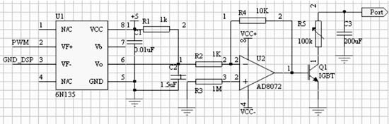
Figure 3 main circuit diagram using AD8072 design
Discharge gap voltage state detecting circuit
In the process of micro-EDM wire cutting, the gap voltage changes with the change of the machining state. By collecting the gap voltage in real time, the machining state in the time period can be known, and the feed direction of the table can be controlled to realize the machining feed. Closed loop control. This not only can effectively control the surface quality after processing, but also can balance the processing efficiency.
For wire cutting, due to the existence of various interference factors, it is inaccurate to judge the state of the gap based on one sampling value. In the design, the method of averaging multiple samples is used, which obviously increases the processing state every time. The cycle, but contradictory is that short-circuit or voltage instability in a short period of time can cause deterioration of the surface roughness after processing, if the system reaction time is too long, the degree is more serious. Therefore, the voltage detection system for microfabrication should have a faster response speed than a general voltage detection system.
After the voltage between the workpiece and the electrode wire is filtered and divided into A/D port of TMS320F2812, the continuously changing analog signal is converted into a discrete digital signal, and the DSP periodically reads the converted digital information and performs corresponding Processing, when the number of read data reaches a prescribed number, the average operation is performed. After the operation is completed, the DSP transmits the averaged voltage value to the upper computer through the asynchronous serial communication circuit.
We can first store the PWM duty cycle requirements in the high and low voltage cases into the TMS320F2812 registers through simulation and experimental results. We can use A/D conversion to detect whether the main circuit is high voltage or low voltage. Then send a command to the TMS320F2812 through the PC to generate the duty cycle of the PWM corresponding to the desired waveform, so that we can better control the voltage cutting waveform on the main circuit wire. In the actual working process of the power supply DSP2812, the DSP spends most of its time on the acquisition, calculation and transmission of the gap voltage information. Only a small amount of time is used for the relay of the pulse power control parameters, which can effectively improve the working efficiency of the DSP. Simulation of wire-cut pulse power supply
This design uses the pspice9.2 software to simulate the main circuit waveform. In the simulation, the current limiting resistors are set to 1, 2, 5 Ω, etc., by setting different resistors and different PWM duty cycles to find the appropriate waveform. As shown in Figure 4, the operator can set the switch to set and stop. The size of the resistance of the main circuit.

Figure 4 main circuit current limiting resistor design

Figure 5 Schematic diagram of the main circuit PSPICE circuit simulation
Previous page next page
Nylon Syringe Filter,0.45 Syringe Filter,Syringe Filter 0.2 Micron,Acrodisc Syringe Filter
Dongguan Boye Instrument & Machinery Equipment Co., Ltd , https://www.boyelab.com