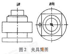
As far as the manufacturing process is concerned, the quality of the product depends mainly on the manufacturing quality and assembly quality of the parts. The manufacturing quality of parts generally uses geometric parameters (such as shape, size, surface roughness), physical parameters (such as conductivity, magnetic permeability, thermal conductivity, etc.), mechanical parameters (such as strength, hardness, etc.) and chemical parameters (such as corrosion resistance). Sex, etc.). The main causes of the machining error of the upper mounting body are: (1) Influence of machine tool error The main factors affecting the machining accuracy of the machine tool are the spindle's rotation accuracy, the linear motion accuracy of the moving parts, and the relative relationship of the forming motion. The accuracy of the spindle's rotation is usually reflected in the radial runout, axial yaw and angular yaw of the spindle, which largely determines the shape accuracy of the machined surface. The milling machining center machine used in this example is the UMC600 universal machining center. Its machine tool precision is currently the top level in the international machining machine tools, and its technical indicators are all within 0.001mm. The processing accuracy of the upper mounting body is less affected. (2) Analysis of fixture positioning error The processing jig for the upper mounting body is positioned by one large flat surface and one positioning pin (diamond pin) and one cylindrical pin. One cylindrical pin limits the movement of x and y and one large plane limits the rotation and movement of z. The locating pin (diamond pin) limits the rotation of x and y and satisfies the six-point positioning principle. Through the positioning error analysis and calculation, it can meet the machining accuracy requirements of parts. The fixture diagram is shown in Figure 2. 2.3 Planning the machining tool path Planning the installation geometry geometry The machining tool path includes the machining blank, the determination of the tool point, the selection of the machining geometry, the selection of the machining tool and the setting of the tool parameters. 2.3.1 Processing of blanks and determination of the point of the tool Before planning the installation of the body geometry shape machining tool path, first use the bounding box command provided by the Mastercam system to determine the blank size required for machining the geometry, and move the center of the graphic to the system coordinate origin, which is convenient for the machining center. . During machining, the position of the workpiece in the machine tool size range is arbitrary. To correctly execute the machining program, the exact position of the workpiece in the machine coordinate system must be determined. The tool point is the reference point for determining the spatial position of the workpiece coordinate system and the machine coordinate system after the workpiece is positioned and clamped on the machine tool and set in the workpiece coordinate system. In the process design and programming, the principle of simple operation and small tool error should be used to set the tool point reasonably. 2.3.2 Planning the machining tool path Planning the mounting geometry The machining tool path mainly includes the selection of the tool, the setting of the tool parameters, the selection of the machining sequence, and the setting of the machining parameters (safety height, lower knife mode, compensation mode, compensation amount, cutting amount, etc.). The type of milling cutter should be compatible with the surface shape and size of the workpiece. According to the heat treatment state, cutting performance and machining allowance of the workpiece material to be processed, selecting a milling cutter with good rigidity and high durability is a prerequisite for fully utilizing the production efficiency of the CNC milling machine and obtaining satisfactory processing quality. The choice of processing route should mainly consider: (1) Minimize the route of the knife, reduce the travel of the air knife, and improve productivity; (2) to ensure the accuracy of the machined parts and surface roughness requirements; (3) Conducive to simplifying the numerical calculation, reducing the number of blocks and the programming workload; (4) The specific value of the cutting amount should be determined according to the specifications of the CNC machine tool, the workpiece material, the processing procedure and other process requirements, and combined with the actual experience. 3 physical machining simulation Before the actual machining of the upper mounting body geometry, the physical machining simulation function provided by Mastercam 9.0 computer software is used to simulate the computer solid processing, which minimizes energy and material consumption and improves processing efficiency. The MasterCAM system generates a tool path file for the machining tool path and tool parameter settings planned by the upper mounting body geometry. The MasterCAM system calls it an NCI file. It is an AscII text format file, which contains all the data of the generated NC code, including coordinate values ​​of a series of tool paths, feed rate, spindle speed, coolant control commands, etc., but it cannot be directly applied to CNC machine tools. After the post-processing program P0ST is converted to the NC code, it can be used by the CNC machine. 4 Conclusion The processing of complex instrument housing parts plays an important role in the mechanical manufacturing industry. In order to improve the machining accuracy and production efficiency of parts, advanced processing methods should be adopted. For CNC machining technology, process processing is an important part of its application. It is related to the correctness and rationality of the processed parts. This paper takes the mounting body on the typical parts as an example to discuss the design of the process design of CNC machining. Reasonable and efficient processing methods and processing routes are of great significance to ensure the processing quality of parts and improve the use efficiency and quality of CNC machine tools. Previous page Milling Type Aluminium Handles A good milling type Aluminium Handle has fine workmanship, no defects and good texture. Feel very comfortable, the owner can choose the handle through electroplating or electrostatic painting. China Milling Type Aluminium Handles have better wear and corrosion resistance. In addition, it also depends on the tension of the milling handle. Generally, the door handle shall be able to accept a tensile force of more than 6kg. In addition, the surface of the milling handle is painted, which has beautiful luster and is not easy to fade and rust. Milling Type Aluminium Handles,Aluminium Profile Handle,Handle Aluminium Kitchen Set,Handle Kitchen Set Aluminium GuangDong XinCheng Material CO.,LTD , https://www.xin-alu.com
2.2 Processing error analysis