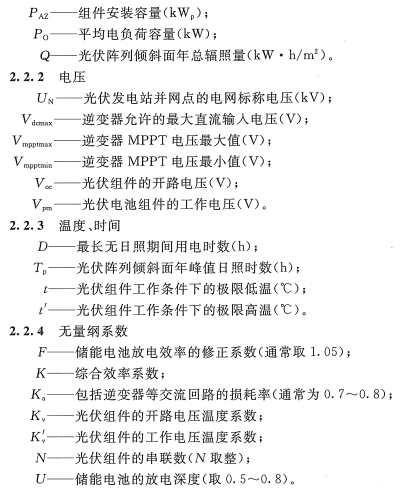
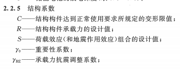
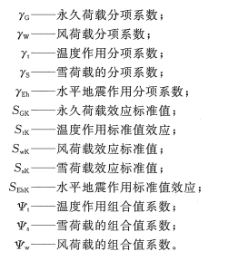
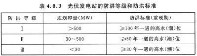
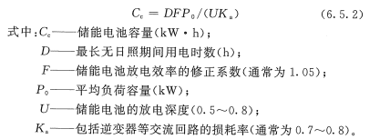
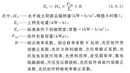
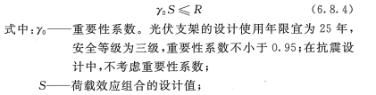
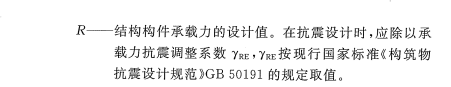
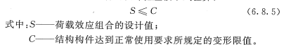
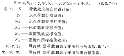
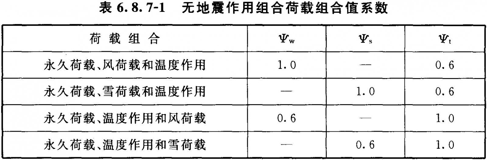
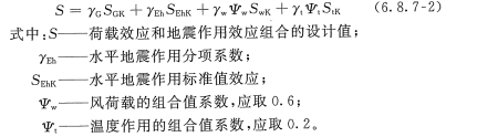
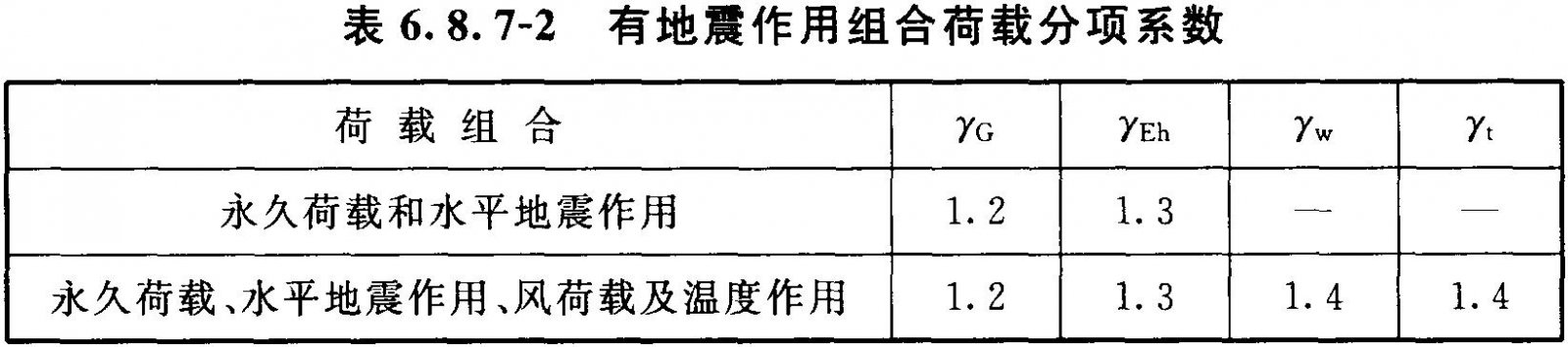
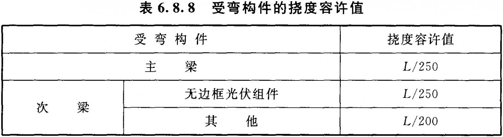
1 General 1.0.1 In order to further implement the relevant national laws, regulations and policies, make full use of solar energy resources, optimize the national energy structure, establish a safe energy supply system, promote the application of photovoltaic power generation technology, regulate the design behavior of photovoltaic power stations, and promote photovoltaic power stations. To build a healthy and orderly development and formulate this code. 1.0.2 This specification applies to newly-built, expanded or rebuilt grid-connected photovoltaic power stations and independent photovoltaic power stations of l00kWp and above. 1.0.3 Feasibility Study of Grid-connected Photovoltaic Power Plant Construction for Access to Power Grid Technical Schemes. 1.0.4 In addition to meeting the requirements of this specification, PV power station design should comply with the relevant national standards. 2 Terms and Symbols 2.1 Terms 2.1.1 PV module PV module With a package and internal connection, can be independently provided with direct current output, the smallest integral solar cell combination device. Also called solar cell module 2.1.2 PV module string photovoltaic modules In a photovoltaic power generation system, several photovoltaic modules are connected in series to form a circuit unit having a certain DC output. 2.1.3 Photovoltaic unit photovoltaic (PV) power unit In PV power stations, a certain number of PV module strings are collected by a DC bus box and boosted by an inverter inverter and an isolation booster transformer to a power source that meets the grid frequency and voltage requirements. Also called unit power module. 2.1.4 Photovoltaic arrays PV array A DC power generating unit is constructed by mechanically and electrically assembling a plurality of photovoltaic modules and having a fixed supporting structure. Also known as photovoltaic arrays. 2.1.5 photovoltaic power generation system photovoltaic (PV) power generation system Utilizing the photovoltaic effect of solar cells, solar radiant energy is directly converted into a power generation system for electrical energy. 2.1.6 Photovoltaic power station photovoltaic (PV) power station Mainly consists of photovoltaic power generation systems, including various types of buildings (structures) and power stations such as maintenance, maintenance, and life support facilities. 2.1.7 Radial connection Each photovoltaic power generation unit is connected to a busbar of a power station using a circuit breaker. 2.1.8 "T" connection tapped connection Several photovoltaic power generation units are connected in parallel and connected to the photovoltaic power station bus through a circuit breaker. 2.1.9 tracking system tracking system Through the rotation of the bracket system, the direction of the incident direction of the sun is tracked in real time, so that the photovoltaic array receives light from the light receiving surface as much as possible to increase the amount of generated power. 2.1.10 Single-axis tracking system single-axis tracking system Rotation around a one-dimensional axis, so that the photovoltaic module light receiving surface in one-dimensional direction as much as possible perpendicular to the incident angle of sunlight tracking system. 2.1.11 Double-axis tracking system A tracking system that rotates about a two-dimensional axis so that the light-receiving surface of the photovoltaic module is always perpendicular to the incident angle of sunlight. 2.1.12 collector line collector line In a distributed and inverting, centralized grid-connected photovoltaic power generation system, the electrical energy output from each photovoltaic module string is fed to the inverter via the combiner box and is collected at the output of the inverter to the DC and AC transmission lines of the generator bus. 2.1.13 point of common coupling (PCC) The connection of more than one user in the grid. 2.1.14 point of coupling (POC) For a photovoltaic power station with a booster station, it refers to the booster station high-voltage bus or node. For a photovoltaic power station without a booster station, it refers to the output summary point of the photovoltaic power station. 2.1.15 Islanding islanding When the grid loses voltage, the photovoltaic power station still maintains the state of power supply to a certain part of the missing piezoelectric network. 2.1.16 Planned islanding intentional islanding According to the pre-set control strategy, there is a planned island phenomenon. 2.1.17 Unintentional islanding phenomenon Unplanned, uncontrolled islanding. 2.1.18 Anti-islanding Prevent the occurrence of unplanned island phenomenon. 2.1.19 peak sunshine hours The total amount of irradiance integrated over a period of time corresponds to the time of continuous irradiation by a light source with an irradiance of 1 kW/m2, in hours (h). 2.1.20 low voltage ride through When the failure or disturbance of the power system causes voltage drop at the photovoltaic power station's grid connection point, the photovoltaic power station can ensure continuous operation without disconnection within a certain voltage drop range and time interval. 2.1.21 annual peak sunshine hours of photovoltaic station The total annual solar radiation received on the PV array is converted into the hour under the irradiance of 1kW/m2. 2.1.22 direct normal irradiance (DNI) The intensity of solar radiation reaching the surface of the Earth's surface perpendicular to the sun's rays. 2.1.23 installation capacity capacity of installation The sum of the nominal power of photovoltaic modules installed in a photovoltaic power plant, measured in Watts (Wp). 2.1.24 watts peak The unit of output power at the maximum power point for photovoltaic modules or photovoltaic arrays under standard test conditions. 2.1.25 true solar time With the solar time standard as the standard timekeeping system, the true solar time is at zero when the daytime center is at the upper center of the earth. 2.2 Symbol 3 Basic regulations 3.0.1 Photovoltaic power plant design should consider factors such as sunshine conditions, land and construction conditions, installation and transportation conditions, and should meet the requirements of safety, reliability, economy, environmental protection, aesthetics, and ease of installation and maintenance. 3.0.2 The design of photovoltaic power stations should give priority to adopting new technologies, new processes, new equipment, and new materials while satisfying safety and reliability. 3.0.3 Field observation devices for solar radiation should be installed in large and medium-sized photovoltaic power stations. 3.0.4 The system configuration of the photovoltaic power station shall ensure that the power quality of the output power complies with the relevant national standards. 3.0.5 Photovoltaic power stations connected to the public power grid shall be equipped with electric energy metering devices approved by the local quality and technical supervision agencies, and shall be put into use after passing the verification. 3.0.6 The photovoltaic power generation system installed on buildings shall not reduce the sunshine standard of adjacent buildings. 3.0.7 The addition of photovoltaic power generation systems to existing buildings must be subject to structural review and electrical safety review, and should meet the safety requirements of the building structure and electrical installations. 3.0.8 Photovoltaic power stations shall be designed for exploration and investigation of the engineering geology of the site and its surrounding areas, and the site topography and geomorphology, structure and distribution of main strata, physical and mechanical properties, and groundwater conditions shall be ascertained. 3.0.9 All equipment and components in photovoltaic power stations shall comply with the relevant provisions of the relevant national standards. The major equipment shall pass the product certification of a certification body approved by the State. 4 site selection 4.0.1 The site selection of photovoltaic power stations shall be based on comprehensive consideration of the national long-term development plan for renewable energy, regional natural conditions, solar energy resources, transportation, access to the power grid, regional economic development planning, and other facilities; In the work, we should start with the overall situation and correctly handle the relationships with neighboring agriculture, forestry, animal husbandry, fisheries, industrial and mining enterprises, urban planning, national defense facilities, and people’s lives. 4.0.2 Photovoltaic power station site selection should be combined with grid structure, power load, traffic, transportation and environmental protection requirements, outlet corridor, geology, earthquake, terrain, hydrology, meteorology, land requisition, demolition, construction and surrounding industrial and mining enterprises to the power station The impact of such conditions, the preparation of a preliminary program, through a comprehensive technical and economic comparison and economic analysis, to provide argumentation and evaluation. When there are multiple candidate sites, the recommended site order should be proposed. 4.0.3 Flood control design for photovoltaic power stations should meet the following requirements: 1 According to different planning capacities, the flood protection rating and flood control standards of photovoltaic power stations shall comply with the requirements of Table 4.0.3. For areas where the ground below the high water level is located, there should be flood protection measures. Flood control measures should be planned in accordance with the planned capacity in the first phase of the project and implemented in phases. 2 When a flood protection embankment (or wave breakwater) is installed at a photovoltaic power station on the seashore, the elevation of its embankment should be in accordance with the flood control standard (return period) in Table 4.0.3 of this Code, and should follow the return period of 50 years. The cumulative increase of 1% of the wave height and the safety of the ultra-high 0.5m are determined. 3 When the flood control embankment is located at a photovoltaic power station next to rivers, rivers, or lakes, the elevation of its embankment shall be determined in accordance with the requirements for the flood control standard (return period) in Table 4.0.3 of this Code, plus a safety extra height of 0.5m; When the influence of wind, waves, and tides is large, it is still necessary to increase the wave height for the 50-year period. (4) When a station is built and a flood protection embankment is installed in a predominantly inner area, the elevation of the embankment shall be determined in accordance with the safety overshoot of the designed inland water level plus 0.5m once in 50 years; when it is difficult to determine, the highest inland water level may be increased by 0.5. m's security is very high. If there is a drainage facility, it should be determined according to the safe height of the designed water level plus 0.5m. 5 For photovoltaic power stations located in mountain areas, measures for preventing mountain floods and flood discharges should be provided. Flood prevention facilities should be designed for flash floods with a frequency of 2%. 6 When there is no flood control embankment in the station area, the elevation of the equipment base and the height of the outdoor floor of the building should not be lower than the flood control standard (return period) in Table 4.0.3 of this code or the highest internal water level in 50 years. Claim. 4.0.4 Sites for ground-based photovoltaic power plants should be selected in areas with flat terrain or low slopes in the north and south. The main direction of the building of the slope roof photovoltaic power station should be south or near to the south, and it is advisable to avoid the obstruction of the photovoltaic components by the surrounding obstacles. 4.0.5 When selecting sites, avoid areas where air is often heavily polluted by suspended solids. 4.0.6 When selecting sites, avoid geological disasters such as dangerous rocks, mudslides, karst development, landslides, and seismogenic fault zones. 4.0.7 When the site selection is within the goaf and its impact scope, a geological disaster risk assessment shall be carried out to comprehensively assess the degree of the geological disaster risk, and an evaluation opinion for the suitability of the construction site shall be proposed and corresponding Precautions. 4.0.8 Photovoltaic power stations should be built in regions with an earthquake intensity of 9 degrees and below. When establishing stations in areas with seismic intensity of 9 degrees or more, earthquake safety evaluation should be conducted. 4.0.9 The sites of photovoltaic power stations should avoid the cultural sites that are mainly protected. They should not be located in open-pit mines or underground shallow mining areas with mining value. When underground sites are deep underground with cultural relics and mineral deposits, in addition to obtaining documents agreed by the cultural relics and mineral resources departments, the sites shall be evaluated for the safety of cultural relics and mineral deposits after excavation. 4.0.10 Photovoltaic power station site selection should use non-arable land and bad land, do not destroy the original water system, do a good job of vegetation protection, reduce earthwork excavation, and save land, reduce house demolition and population migration. 4.0.11 Photovoltaic power station site selection should consider the access corridor of the power system when the power station reaches the planned capacity. 4.0.12 When conditions are right, photovoltaic power stations can be built in wind farms. 5 Solar Energy Analysis 5.1 General provisions 5.1.1 Design of photovoltaic power station The basic status of regional solar energy resources at the site where the site is located shall be analyzed, and adaptive analysis shall be conducted on the relevant geographical conditions and climate characteristics. 5.1.2 When analyzing solar energy resources such as total solar radiation and its changing trend for photovoltaic power stations, weather stations with long-term solar radiation observation records near the site of the site should be selected as reference weather stations. 5.1.3 When using on-site observation data for solar energy resource analysis, the on-site observation data shall be continuous and shall not be less than one year. 5.1.4 In the early stage of construction of a large-scale photovoltaic power station, a solar radiation field observation station should be established at the site of the site, and the period of on-site observation records should not be less than one complete year. 5.2 Reference weather station basic conditions and data acquisition 5.2.1 The reference weather station shall have a long-term observation record of solar radiation for more than 10 years. 5.2.2 The climatic characteristics and geographical characteristics of the location of the reference weather station and the location of the photovoltaic power station should be basically the same. 5.2.3 The radiation observation data of the reference weather station and the radiation observation data of the solar radiation observation device at the site of the photovoltaic power station should have good correlation. 5.2.4 The information collected by the referenced weather station should include the following: 1 The basic conditions and time adopted by the meteorological station for long-term observation and recording of standards, models of radiation instruments, installation locations, elevations, and surrounding environmental conditions, as well as site relocation, radiation equipment maintenance records, and surrounding environmental changes since the establishment of the station. 2 Observing records of the total amount of radiation, direct radiation, scattered radiation, and sunshine hours for each consecutive month or more for more than 10 consecutive years, and the hourly observation record for at least one complete year at the same time as the site observation station on site. 3 The average of the maximum irradiance for each month and month of the last 10 consecutive years. 4 The multi-year monthly average temperature, extreme maximum temperature, extreme minimum temperature, maximum temperature in daytime and minimum daytime temperature in the past 30 years. 5 Average wind speed for many years, years of great wind speed and time of occurrence, dominant wind direction, years of maximum permafrost depth and snow thickness, and annual average precipitation and evaporation. 6 Severe weather conditions such as continuous rainy days, thunderstorm days, hail times, dust storms, and strong winds in the past 30 years. 5.3 Basic Requirements for Solar Radiation Field Observation Stations 5.3.1 The solar radiation field observation station should be set up at the site of the photovoltaic power station. The observation content should include the measured time of total radiation, direct radiation, scattered radiation, maximum irradiance, temperature, humidity, wind speed, and wind direction. The sequence data shall be installed and observed and recorded in real time in accordance with the provisions of the current industry standard "Regulations for Surface Meteorological Observations" QX/T 55. 5.3.2 For large-scale photovoltaic power stations with photovoltaic arrays arranged at optimal fixed inclination angles, solar radiation observation items at the optimum fixed inclination angles determined by design should be added. 5.3.3 For large-scale photovoltaic power stations with inclined single-axis or flat single-axis tracking devices, additional solar radiation observation items should be added to the design determined oblique single-axis or flat uniaxial tracking light-receiving surface. 5.3.4 For high-power concentrating photovoltaic power stations, increase the number of observations for direct radiation irradiance (DNI). 5.3.5 Real-time observation data on the site should be transmitted directly through a wired or wireless communication channel. 5.4 Verification and Analysis of Solar Radiation Observation Data 5.4.1 The integrity of solar radiation observation data should be tested, and observation data should meet the following requirements: 1 The time series of observations for real-time observations should be in the same order as expected. 2 The amount of observation data recorded in real-time in a certain time sequence should be equal to the amount of data expected to be recorded. 5.4.2 The observation data of solar radiation should be tested according to the daily astronomical radiation, and the observation data should meet the following requirements: 1 Total radiation maximum irradiance less than 2kW/m2 2 The scattered radiation value is less than the total radiation value. The total amount of radiation on the 3rd is less than the possible total amount of daily radiation, and the total amount of possible daily radiation shall comply with the provisions of Appendix A of this Code. 5.4.3 After the integrity and reasonableness of the observation data of solar radiation, the data of irrationality and lack of measurement should be corrected and supplemented. Other reference data recorded during the same period can be filled with invalid or missing data after analysis and processing to form complete long-sequence observation data. 5.4.4 Analysis of photovoltaic power station solar energy resources should include the following: 1 The annual total radiation changes over a long period of time and the interannual changes in total monthly radiation. 2 The average annual total radiation dose over 10 years and the monthly average total radiation dose. 3 The daily change of radiation amount in each month for the past three consecutive months and the hourly change of radiation amount on the typical day of each month. 4 Total radiation maximum irradiance. 5.4.5 When PV arrays are installed with fixed inclination, single sloping axis, flat uniaxial, and inclined vertical single or dual axis tracking, fixed angles and inclined orders should be based on the average annual total radiation forecast within the service life of the plant. Axis, flat uniaxial, oblique vertical single or dual axis tracking Average annual total radiation dose on the light receiving surface. 6 Photovoltaic power generation system 6.1 General provisions 6.1.1 The power generation system of large and medium-sized ground photovoltaic power stations should adopt multi-level confluence, decentralized inversion, and centralized grid-connected systems; after dispersion and inversion, local boost should be adopted, and the number and voltage level of the collector circuit after boosting should be Determined after technical and economic comparison. 6.1.2 In photovoltaic power generation systems, the voltage, array orientation, and installation inclination of the PV modules connected to the same inverter should be the same. 6.1.3 The design voltage of the DC side of the PV system shall be higher than the maximum open circuit voltage of the PV modules at the local daytime extreme temperatures. The maximum allowable voltage of the equipment and materials used in the system shall not be lower than the design voltage. 6.1.4 The configuration capacity of the inverter in the PV system shall be matched with the installation capacity of the PV array, and the maximum DC input power allowed by the inverter shall not be less than the actual maximum DC output power of the corresponding PV array. 6.1.5 The maximum power operating voltage range of PV array strings shall be within the maximum power tracking voltage range of the inverter. 6.1.6 The installation capacity of an independent photovoltaic power generation system shall be determined according to the required power of the load and the local sunshine conditions. 6.1.7 Photovoltaic array design should facilitate the cleaning of the surface of photovoltaic modules. When the site of the site is poor in atmospheric environment, the surface of components is highly polluted, and there is no self-cleaning ability, a cleaning system or cleaning equipment should be installed. 6.2 Classification of Photovoltaic Power Generation Systems 6.2.1 Photovoltaic power generation systems can be classified into grid-connected photovoltaic power generation systems and stand-alone photovoltaic power generation systems according to whether they are connected to the public power grid. 6.2.2 The grid-connected photovoltaic power generation system can be divided into user-side photovoltaic power generation systems and grid-side photovoltaic power generation systems according to different access points. 6.2.3 The photovoltaic power generation system can be divided into the following three types of systems according to the installation capacity: 1 Small-scale photovoltaic power generation system: The installation capacity is less than or equal to 1MWp. 2 Medium-sized photovoltaic power generation systems: installation capacity greater than 1MWp and less than or equal to 30MWp. 3 large-scale photovoltaic power generation system: installation capacity is greater than 30MWp. 6.2.4 Photovoltaic power generation systems can be divided into photovoltaic power generation systems and ground photovoltaic power generation systems combined with buildings according to whether they are combined with buildings. 6.3 Major Equipment Selection 6.3.1 Photovoltaic modules can be classified into crystalline silicon photovoltaic modules, thin film photovoltaic modules and condenser photovoltaic modules. 6.3.2 Photovoltaic modules should be selected based on technical conditions such as type, peak power, conversion efficiency, temperature coefficient, component size and weight, and power irradiance characteristics. 6.3.3 Photovoltaic modules shall be checked for performance parameters based on ambient conditions such as solar irradiance and working temperature. 6.3.4 The type of PV module should be selected according to the following conditions: 1 Based on factors such as solar radiation, climate characteristics, site area, and other factors, it is determined by comparison of technology and economy. 2 Crystal silicon photovoltaic modules or condenser photovoltaic modules should be used in areas with high solar radiation and large direct components. 3 Thin-film PV modules should be used in areas with low solar radiation, large scattering components, and high ambient temperatures. 4 In photovoltaic power generation systems combined with buildings, when the technology is economically reasonable, photovoltaic modules that are coordinated with the building structure should be selected. Building materials photovoltaic modules should meet the technical requirements of the corresponding building materials or components. 6.3.5 The performance of the inverter used in the grid-connected photovoltaic power generation system shall meet the requirements of the relevant technical requirements for access to the public power grid, and shall have continuously adjustable functions of active power and reactive power. Inverters for large and medium-sized photovoltaic power stations should also have low voltage ride-through. 6.3.6 Inverter shall be of type, capacity, phase number, frequency, cooling method, power factor, overload capacity, temperature rise, efficiency, input voltage output, MPPT, protection and monitoring functions, communication Select technical conditions such as interface and protection level. 6.3.7 The inverter shall be calibrated according to environmental conditions such as ambient temperature, relative humidity, altitude, seismic intensity, and pollution level. 6.3.8 Inverters that are used in the humid tropical zone, where there is serious industrial pollution, and along beach areas, should consider the effects of moisture, pollution, and salt spray. 6.3.9 Inverters used at altitudes of 2000m above sea level should use high prototype (G) products or use derating measures. 6.3.10 The combiner box shall be selected according to the technical conditions such as type, insulation level, voltage, temperature rise, protection level, number of input circuits output, and rated output current. 6.3.11 The convergence box shall be checked for performance parameters according to environmental conditions such as ambient temperature, relative humidity, altitude, pollution level, and seismic intensity. 6.3.12 The combiner box shall have the following protection functions: 1 lightning protection device should be set. 2 The input loop of the combine box should have anti-backflow and over-current protection; for the multi-stage converging photovoltaic power generation system, if the front stage has anti-backflow protection, then the latter stage can not do anti-backflow protection. 3 The output loop of the combine box should have isolation protection measures. 4 should set the monitoring device. 6.3.13 Outdoor confluence boxes shall be provided with measures such as anti-corrosion, anti-rust and anti-exposure, and the protection level of the confluent box shall not be lower than IP54. 6.4 Photovoltaic phalanx 6.4.1 Photovoltaic square arrays can be classified into two types: fixed type and track type. The choice of method should be determined by technical and economic comparison based on installation capacity, installation site area and characteristics, type of load and operation management method. 6.4.2 In the photovoltaic array, the electrical performance parameters of the photovoltaic modules in the same PV module string should be consistent. The number of PV module strings in series should be calculated according to the following formula: 6.4.3 In the case of a fixed arrangement of photovoltaic arrays, the optimal inclination should be combined with the site's local conditions, such as multi-year monthly average irradiance, direct component irradiance, scattered component irradiance, wind speed, rain, and snow conditions. Design, and should meet the following requirements: 1 For grid-connected PV systems, the dip angle should maximize the annual exposure to the inclined plane of the PV array. 2 For an independent photovoltaic power generation system, the inclination should be such that the minimum irradiance of the photovoltaic array is exposed to a larger amount of radiation on the month's inclined surface. 3 For photovoltaic power stations with special requirements or high land costs, the design dip and array line spacing of the PV arrays can be determined after technical and economic comparison according to actual needs. 6.5 Energy Storage System 6.5.1 The independent photovoltaic power station shall be equipped with energy storage devices of appropriate capacity and meet the requirements for providing continuous and stable power to the load. Grid-connected photovoltaic power stations can be equipped with energy storage devices of appropriate capacity according to actual needs. 6.5.2 The capacity of an energy storage system configured for an independent photovoltaic power plant shall be determined based on local sunshine conditions, continuous rainy days, the electrical energy requirements of the load, and the technical characteristics of the stored energy storage battery. The capacity of the energy storage battery should be calculated as follows: 6.5.3 The energy storage battery used in photovoltaic power stations should be selected based on technical conditions such as energy storage efficiency, cycle life, energy density, power density, response time, environmental adaptability, charge and discharge efficiency, self-discharge rate, and deep discharge capability. . 6.5.4 Photovoltaic power plant energy storage system should use on-line detection device for intelligent real-time detection, should have on-line identification of battery pack behind monomer, determine the overall performance of energy storage battery, charge and discharge management functions, should have human-machine interface and communication interface. 6.5.5 Photovoltaic power station energy storage system should use large-capacity monomer storage batteries, reduce the number of parallel connections, and should use energy storage battery component group to control charge and discharge. 6.5.6 The charging controller shall select according to technical conditions such as type, rated voltage, rated current, input power, temperature rise, protection level, number of input circuits, charging and discharging voltage, and protection function. 6.5.7 The charge controller shall be calibrated according to environmental conditions such as ambient temperature, relative humidity, altitude, and seismic intensity. 6.5.8 The charge controller shall have short-circuit protection, overload protection, battery over-charge (discharge) protection, under (over) pressure protection and lightning protection. It shall have temperature compensation, data acquisition and communication functions when necessary. 6.5.9 The charge controller should use low energy consumption and energy-saving products. 6.6 Calculation of power generation 6.6.1 The prediction of PV power generation capacity shall be based on the solar energy resources at the site of the site, and shall be determined after considering various factors such as PV power station system design, PV array layout and environmental conditions. 6.6.2 The on-grid electricity of photovoltaic power stations can be calculated as follows: 6.7 Tracking System 6.7.1 Tracking system can be divided into single-axis tracking system and dual-axis tracking system. 6.7.2 The tracking system control mode can be divided into active control mode, passive control mode and compound control mode. 6.7.3 The design of the tracking system should meet the following requirements: 1 The bracket of the tracking system should take corresponding protective measures according to the characteristics of different regions. 2 tracking system should have a communication port. 3 During the operation of the tracking system, the distance between the bottom of the photovoltaic array assembly and the ground should not be less than 300mm. 6.7.4 The selection of the tracking system should meet the following requirements: 1 The selection of the tracking system should be based on factors such as the environment and climate characteristics of the installation site, and be determined after the technical and economic comparison. 2 Horizontal single-axis tracking system should be installed in low latitude areas. 3 Inclined single-axis and inclined vertical single-axis tracking system should be installed in the middle and high latitudes. 4 Dual-axis tracking system should be installed in the middle and high latitudes. 5 It is not advisable to use passive control tracking systems in areas where the sensors are easily contaminated. 6 It is recommended to have the function of adjusting the angle of the tracking system to the minimum position of the wind by remote control in an emergency. 6.7.5 Tracking system tracking accuracy should meet the following requirements: 1 The tracking accuracy of a single-axis tracking system should not be less than ±5°. 2 The tracking accuracy of the two-axis tracking system should not be less than ±2°. The tracking accuracy of the 3-line focus tracking system should not be less than ±1°. The tracking accuracy of the 4-point focus tracking system should not be less than ±0.5°. 6.8 PV Bracket 6.8.1 Photovoltaic supports shall be combined with the actual selection of materials, design of structural plans and construction measures to ensure that the support structure meets strength, stability, and stiffness requirements during transportation, installation, and use, and meets the requirements of seismic, wind, and corrosion resistance. 6.8.2 Photovoltaic stent materials should be made of steel. The selection of materials and stent design should comply with the provisions of the current national standard "Steel Structure Design Code" GB 50017. 6.8.3 The strength, stability and connection strength of structures and members shall be calculated according to the limit state of the bearing capacity, and the deformation of the structures and members shall be calculated according to the limit state of normal use. 6.8.4 When designing structural members according to the limit state of the bearing capacity, the basic or accidental combination of load effects shall be used. The design value of the load effect combination should be checked as follows: 6.8.5 When designing structural members according to normal use limit conditions, a standard combination of load effects shall be used. The design value of the load effect combination should be checked as follows: 6.8.6 In earthquake-proof areas, the support shall be checked for earthquake resistance. 6.8.7 The calculation of the load and load effect of the support shall comply with the following provisions: 1 The wind load, snow load and temperature load shall be taken as the value of the load in the case of 25 years in the current national standard "Code for the design of building structures" GB 50009. The weight coefficient of the wind load on the ground and roof supports is 1.3. The determination of the wind load on the facade of a building shall comply with the requirements of the current national standard “Code for the loading of building structures†GB 50009. 2 In the absence of seismic effect combinations, the design value of the combined load effect shall be as follows: Calculation: (3) When there is no seismic effect combination, the load sub-components used in displacement calculation shall be taken as 1.0; when the bearing capacity is calculated, the combined value of non-earthquake-acting loads shall meet the requirements of Table 6.8.7-1. 4 When there are combinations of seismic effect effects, the design values ​​of the load effect combinations should be calculated as follows: (5) When there are combinations of seismic effects, the partial load factors used in the displacement calculation shall all be taken as 1.0; when the bearing capacity is calculated, the load partial coefficients of the combination of seismic actions shall comply with the requirements of Table 6.8.7-2. Note: 1YG: When the permanent load effect is favorable to the structural bearing capacity, it should take 1.0; 2 The "one" in the table indicates that the load or effect of the effect is not considered in the combination. 6 When designing the support, check the construction and maintenance load, and meet the following requirements: 1) The construction maintenance load should be taken as 1 kN, and it can also be taken as the actual load and act on the most unfavorable position of the support; 2) When carrying out the bearing component bearing capacity calculation, the load combination should take the permanent load and the construction maintenance load, the partial factor of the permanent load is taken as 1.2, and the partial factor of the construction or maintenance load is taken as 1.4; 3) When carrying out the verification of the displacement of the bracket components, the load combination shall be taken as the permanent load and the construction maintenance load. The partial factor shall be taken as 1.0. 6.8.8 The deformation of steel brackets and components shall meet the following requirements: 1 The wind load is taken as a standard value or under earthquake, the displacement of the column top should not be greater than 1/60 of the column height. 2 The bending tolerance of bending members should not exceed the provisions of Table 6.8.8. Note: L is the span of the bending member. For cantilever beams, L is 2 times the overhang length. 6.8.9 The construction of steel brackets shall comply with the following provisions: 1 The plate thickness used for the secondary beam should not be less than 1.5mm. The plate thickness used for the main beam and the column should not be less than 2.5mm. When there is a reliable basis, the plate thickness can be taken as 2mm. 2 The slenderness ratio of the pressed and tensioned members shall be in accordance with Table 6.8.9. Note: For structures subject to static loading, only the slenderness ratio of the tension member in the vertical plane can be calculated. Corrosion protection of 6.8.10 brackets shall meet the following requirements: 1 The bracket should be easy to check and clean. 2 The anti-corrosion of steel brackets should adopt hot-dip galvanizing. The average thickness of galvanized layer should not be less than 55μm. 3 When aluminum alloy materials are in contact with and tightened with other metal materials other than stainless steel or with acids and alkaline non-metallic materials, isolation measures should be taken. 4 Aluminium alloy brackets should be surface-preserved and can be anodized. The minimum thickness of the anodized film should be in accordance with Table 6.8.10. 6.9 Concentrating Photovoltaic System 6.9.1 Concentrating photovoltaic systems shall include concentrating and tracking systems. 6.9.2 Line focus Concentration should adopt single-axis tracking system, and spot-focus concentrating should adopt dual-axis tracking system. 6.9.3 The selection of concentrator photovoltaic systems should meet the following requirements: 1 The line-focus concentrating photovoltaic system using a horizontal single-axis tracking system should be installed in areas with low latitude and direct light components. 2 The line-focusing concentrating photovoltaic system with a tilted single-axis tracking system should be installed in areas with large direct light components at high latitudes. The 3-point focus concentrating photovoltaic system should be installed in areas with large direct light components. 6.9.4 Concentrating photovoltaic systems for photovoltaic power stations shall meet the following requirements: 1 Optical components should be certified by the relevant national certification bodies and have good heat dissipation performance. 2 It has effective protective measures and should ensure the safe and long-term operation of the equipment in the local extreme environment. 3 Tracking system for low magnification, its tracking accuracy should not be less than ± 10, for high-power spotlight tracking system, its tracking accuracy should not be less than ± 0.5 °. 7 station layout 7.1 General layout of station area 7.1.1 The general plane of the station area of ​​photovoltaic power station should be arranged according to the production, construction and living needs of the power station, combined with the natural conditions and construction plans of the site and nearby areas, and deal with the station area water supply and drainage facilities, transportation, and outlets. Corridors and other researches are conducted based on the near-term, far, near, and integrated planning. 7.1.2 The general layout of photovoltaic power plant station should implement the principle of land saving. Through optimization, the area of ​​production land, residential land and construction land of the whole station should be controlled; the scope of land use should be determined according to the planned capacity according to the needs of construction and construction. , Should be divided, requisitioned and leased in batches. 7.1.3 The general layout of the station area of ​​a photovoltaic power station shall include the following: 1 Photovoltaic matrix. 2 booster station (or switch station). 3 stations within the collection circuit. 4 local inverter booster station. 5 stations within the road. 6 Other protective facilities (flood protection, lightning protection, fire protection). 7.1.4 The general layout of the station area of ​​photovoltaic power stations shall meet the following requirements: 1 Convenient transportation. 2 Coordinating the relationship between stations and stations, production and living, production and construction. 3 Coordinate with town or industrial park planning. 4 Convenient for construction and favorable for expansion. 5 rational use of terrain, geological conditions. 6 Reduce the amount of earthwork on the site. 7 Reduce project cost, reduce operating costs, and increase economic efficiency. 7.1.5 The general layout of the station area of ​​photovoltaic power stations shall also meet the following requirements: 1 The buildings within the station should be arranged in conjunction with the direction of the sun, reasonably compact; auxiliary, auxiliary buildings and administrative buildings should adopt a joint arrangement. 2 Greening planning should be carried out according to local conditions, and trees should be planted and planted using free space. The rate of green space should meet the greening requirements of the local planning department. 3 The location of the booster station (or switch station) and the buildings within the station shall be determined according to the layout of the PV array, the scheme of the access system, terrain, geology, traffic, production, life, and safety. 4 The arrangement of the collector circuit within the station shall be determined according to the arrangement of the photovoltaic array, the position of the booster station (or switchyard) and the distance, capacity, and safety distance of the single-circuit collector circuit. 5 The roads within the station should be able to meet the requirements for transportation, installation, operation and maintenance of the equipment, and retain the work surface that can be overhauled and hoisted. 7.1.6 Large and medium-sized terrestrial photovoltaic power station stations can have two outbound populations, and their locations should be easily accessible both inside and outside the station. The width of the traffic section of the main road of the station out of the population should be the same as the connecting road. It should adopt 6m; the secondary road (ring road) width should adopt 4m. The width of the pedestrian approach road leading to the building’s outpost should be compatible with the width of the gate. 7.1.7 The main inbound roads of the ground photovoltaic power station should be connected to the existing road to the town. The connection should be short and convenient and it should be easy to avoid crossing with the railway line. Roads, fire truck lanes, and sidewalks should be set up between buildings in the station area in accordance with the needs of production, life, and firefighting. The main roads in the station can be muddy gravel roads, concrete roads or asphalt roads. 7.1.8 The vertical layout of photovoltaic power station station area should be determined based on production requirements, engineering geology, hydro-meteorological conditions, site elevation and other factors, and should meet the following requirements: 1 In station areas without embankments or dike, the outdoor floor elevation of the booster station (or switchyard) area should be higher than the design high water level by 0.5m. 2 The determination of the elevation of all buildings, structures, roads, etc. shall meet the convenience of production and use. The elevations and arrangements of foundations, pipelines, pipe racks, trenches, tunnels, and basements in ground and underground facilities shall be arranged in a unified manner, reasonably intersected, and facilitated by maintenance and expansion, and drainage shall be smooth. 3 The amount of engineering earth and rock works should be reduced, the cost of foundation treatment and site leveling should be reduced, and the amount of fill and excavation should be balanced. When the amount of filling and excavation cannot be balanced, the borrowing or abandonment of the site should be implemented. The minimum slope and aspect of the 4 station area should be based on the principle of quicker elimination of surface water. It should be compatible with the setting of stormwater wells and stormwater outlets in buildings, roads and sites, and be based on local rainfall and site conditions. Factors are determined. 5地处山å¡åœ°åŒºå…‰ä¼å‘电站的竖å‘布置,应在满足工艺è¦æ±‚çš„å‰æ下,åˆç†åˆ©ç”¨åœ°å½¢ï¼ŒèŠ‚çœåœŸçŸ³æ–¹é‡å¹¶ç¡®ä¿è¾¹å¡ç¨³å®šã€‚ 7.1.9ç«™åŒºåœºåœ°æŽ’æ°´ç³»ç»Ÿåº”æ ¹æ®åœ°å½¢ã€å·¥ç¨‹åœ°è´¨ã€åœ°ä¸‹æ°´ä½ç‰å› ç´ è¿›è¡Œè®¾è®¡ï¼Œå¹¶åº”ç¬¦åˆä¸‹åˆ—è¦æ±‚: 1场地的排水系统应按规划容é‡è¿›è¡Œè®¾è®¡ï¼Œå¹¶ä½¿æ¯æœŸå·¥ç¨‹æŽ’水畅通。 2室外沟é“高于设计地åªæ ‡é«˜æ—¶ï¼Œåº”有过水措施,或在沟é“的两侧设排水设施。 3对建在山区或丘陵地区的光ä¼å‘电站,在站区边界处应有防æ¢å±±æ´ªæµå…¥ç«™åŒºçš„设施。 7.1.10生产建ç‘物底层地é¢æ ‡é«˜ï¼Œå®œé«˜å‡ºå®¤å¤–地é¢è®¾è®¡æ ‡é«˜150mm-300mmï¼Œå¹¶åº”æ ¹æ®åœ°è´¨æ¡ä»¶è®¡äººå»ºç‘物沉é™çš„å½±å“。 7.1.11å…‰ä¼å‘电站的交通è¿è¾“ã€ä¾›æ°´å’ŒæŽ’æ°´ã€è¾“电线路ç‰ç«™å¤–设施,应在确定站å€å’Œè½å®žç«™å†…å„个主è¦ç³»ç»Ÿçš„åŸºç¡€ä¸Šï¼Œæ ¹æ®è§„划容é‡å’Œç«™å€çš„自然æ¡ä»¶è¿›è¡Œç»¼åˆè§„划。 7.1.12应结åˆå·¥ç¨‹å…·ä½“æ¡ä»¶ï¼Œåšå¥½å…‰ä¼å‘电站的防排洪(æ¶ï¼‰è§„划,充分利用现有防排洪(æ¶ï¼‰è®¾æ–½ã€‚当必须新建时,å¯å› 地制宜地选用防洪(æ¶ï¼‰å ¤ã€æŽ’洪(æ¶ï¼‰æ²Ÿæˆ–挡水围墙。 7.1.13å…‰ä¼å‘ç”µç«™çš„å‡ºçº¿èµ°å»Šï¼Œåº”æ ¹æ®ç³»ç»Ÿè§„划ã€è¾“电线出线方å‘ã€ç”µåŽ‹ç‰çº§å’Œå›žè·¯æ•°ï¼ŒæŒ‰å…‰ä¼å‘电站规划容é‡ï¼Œå…¨é¢è§„划,é¿å…交å‰ã€‚ 7.1.14å…‰ä¼å‘电站的施工区应按规划容é‡ç»Ÿç¹è§„åˆ’ï¼Œå¹¶åº”ç¬¦åˆ ä¸‹åˆ—è¦æ±‚: 1布置应紧凑åˆç†ï¼ŒèŠ‚çœç”¨åœ°ã€‚ 2应按施工æµç¨‹çš„è¦æ±‚安排施工临时建ç‘ã€ææ–™è®¾å¤‡å †ç½®åœºã€æ–½å·¥ä½œä¸šåœºæ‰€åŠæ–½å·¥ä¸´æ—¶ç”¨æ°´ã€ç”¨ç”µå¹²çº¿è·¯å¾„。 3施工场地排水系统宜å•ç‹¬è®¾ç½®ï¼Œæ–½å·¥é“路宜永临结åˆã€‚ 4利用地形,å‡å°‘场地平整土石方é‡ï¼Œå¹¶åº”é¿å…施工区场地表土层的大é¢ç§¯ç ´å,防æ¢æ°´åœŸæµå¤±ã€‚ 7.2å…‰ä¼æ–¹é˜µå¸ƒç½® 7.2.1å…‰ä¼æ–¹é˜µåº”æ ¹æ®ç«™åŒºåœ°å½¢ã€è®¾å¤‡ç‰¹ç‚¹å’Œæ–½å·¥æ¡ä»¶ç‰å› ç´ åˆç†å¸ƒç½®ã€‚大ã€ä¸åž‹åœ°é¢å…‰ä¼å‘电站的光ä¼æ–¹é˜µå®œé‡‡ç”¨å•å…ƒæ¨¡å—化的布置方å¼ã€‚ 7.2.2地é¢å…‰ä¼å‘电站的光ä¼æ–¹é˜µå¸ƒç½®åº”满足下列è¦æ±‚: 1固定å¼å¸ƒç½®çš„å…‰ä¼æ–¹é˜µã€å…‰ä¼ç»„件安装方ä½è§’宜采用æ£å—æ–¹å‘。 2å…‰ä¼æ–¹é˜µå„排ã€åˆ—的布置间è·åº”ä¿è¯æ¯å¤©9:00-15:00(当地真太阳时)时段内å‰ã€åŽã€å·¦ã€å³äº’ä¸é®æŒ¡ã€‚ 3å…‰ä¼æ–¹é˜µå†…å…‰ä¼ç»„件串的最低点è·åœ°é¢çš„è·ç¦»ä¸å®œä½ŽäºŽ300mmï¼Œå¹¶åº”è€ƒè™‘ä»¥ä¸‹å› ç´ ï¼š 1)当地的最大积雪深度; 2)当地的洪水水ä½ï¼› 3)æ¤è¢«é«˜åº¦ã€‚ 7.2.3与建ç‘相结åˆçš„å…‰ä¼å‘电站的光ä¼æ–¹é˜µåº”结åˆå¤ªé˜³è¾ç…§åº¦ã€é£Žé€Ÿã€é›¨æ°´ã€ç§¯é›ªç‰æ°”候æ¡ä»¶åŠå»ºç‘æœå‘ã€å±‹é¡¶ç»“æž„ç‰å› ç´ è¿›è¡Œè®¾è®¡ï¼Œç»æŠ€æœ¯ç»æµŽæ¯”较åŽç¡®å®šæ–¹ä½è§’ã€å€¾è§’和阵列行è·ã€‚ 7.2.4大ã€ä¸åž‹åœ°é¢å…‰ä¼å‘电站的逆å˜å‡åŽ‹å®¤å®œç»“åˆå…‰ä¼æ–¹é˜µå•å…ƒæ¨¡å—化布置,宜采用就地布置方å¼ã€‚逆å˜å‡åŽ‹å®¤å®œæ ¹æ®å·¥è‰ºè¦æ±‚布置在光ä¼æ–¹é˜µå•å…ƒæ¨¡å—çš„ä¸éƒ¨ï¼Œä¸”é 近主è¦é€šé“处。 7.2.5工艺管线的敷设方å¼åº”符åˆä¸‹åˆ—è¦æ±‚: 1工艺管线和管沟宜沿é“路布置。地下管线和管沟一般宜敷设在é“路行车部分之外。 2电缆ä¸åº”与其他管é“åŒæ²Ÿæ•·è®¾ã€‚ 3管沟ã€åœ°ä¸‹ç®¡çº¿ä¸Žå»ºç‘物ã€é“è·¯åŠå…¶ä»–管线的水平è·ç¦»ä»¥åŠç®¡çº¿äº¤å‰æ—¶çš„åž‚ç›´è·ç¦»ï¼Œåº”æ ¹æ®åœ°ä¸‹ç®¡çº¿å’Œç®¡æ²Ÿçš„埋深ã€å»ºç‘ç‰©çš„åŸºç¡€æž„é€ åŠæ–½å·¥ã€æ£€ä¿®ç‰å› ç´ ç»¼åˆç¡®å®šã€‚ 7.3站区安全防护设施 7.3.1å…‰ä¼å‘电站宜设置安全防护设施,该设施宜包括:人侵报è¦ç³»ç»Ÿã€è§†é¢‘安防系统和出人å£æŽ§åˆ¶ç³»ç»Ÿç‰ï¼Œå¹¶èƒ½ç›¸äº’è”动。 7.3.2安装于室外的安全防护设施应采å–防雷ã€é˜²å°˜ã€é˜²é›¨ã€é˜²å†»ç‰æŽªæ–½ã€‚ 7.3.3人侵报è¦ç³»ç»Ÿè®¾è®¡åº”按下列è¦æ±‚进行: 1人侵报è¦ç³»ç»Ÿè®¾ç½®åº”符åˆçŽ°è¡Œå›½å®¶æ ‡å‡†ã€Šäººä¾µæŠ¥è¦ç³»ç»Ÿå·¥ç¨‹è®¾è®¡è§„范》GB 50394的规定。 2人侵报è¦ç³»ç»Ÿåº”能与视频监控系统ã€å‡ºäººå£æŽ§åˆ¶ç³»ç»Ÿç‰è”动。防范区内人侵探测器的设置ä¸å¾—有盲区,系统除应具有本地报è¦åŠŸèƒ½å¤–,还宜具有异地报è¦åŠŸèƒ½ã€‚ 3人侵报è¦ç³»ç»Ÿçš„ä¿¡å·ä¼ 输å¯é‡‡ç”¨ä¸“ç”¨æœ‰çº¿ä¼ è¾“ä¸ºä¸»ã€æ— 线信é“ä¼ è¾“ä¸ºè¾…çš„ä¼ è¾“æ–¹å¼ã€‚控制信å·ç”µç¼†åŠç”µæºçº¿è€åŽ‹ç‰çº§ã€å¯¼çº¿åŠç”µç¼†èŠ¯çº¿çš„截é¢ç§¯å‡åº”æ»¡è¶³ä¼ è¾“è¦æ±‚。 4系统报è¦åº”有记录,并能按时间ã€åŒºåŸŸã€éƒ¨ä½ä»»æ„编程设防和撤防。系统应具有设备防拆功能ã€ç³»ç»Ÿè‡ªæ£€åŠŸèƒ½åŠæ•…障报è¦åŠŸèƒ½ã€‚ 5主控室内应装有紧急按钮。紧急按钮的设置应éšè”½ã€å®‰å…¨å¹¶ä¾¿äºŽæ“作,且应具有防误触å‘ã€è§¦å‘报è¦è‡ªé”ã€äººå·¥å¤ä½ç‰åŠŸèƒ½ã€‚ 7.3.4视频安防监控系统设计应符åˆä¸‹åˆ—è¦æ±‚: 1视频安防监控系统设置应符åˆçŽ°è¡Œå›½å®¶æ ‡å‡†ã€Šè§†é¢‘安防监控系统工程设计规范》GB 50395的规定,并应具有对图åƒä¿¡å·çš„分é…ã€åˆ‡æ¢ã€å˜å‚¨ã€è¿˜åŽŸã€è¿œä¼ ç‰åŠŸèƒ½ã€‚ 2系统设计应满足监控区域有效覆盖ã€å¸ƒå±€åˆç†ã€å›¾åƒæ¸…æ™°ã€æŽ§åˆ¶æœ‰æ•ˆçš„è¦æ±‚。 3视频监控系统宜与ç¯å…‰ç³»ç»Ÿè”动。监视场所的最低环境照度应高于摄åƒæœºè¦æ±‚最低照度(çµæ•åº¦ï¼‰çš„10å€ï¼Œå½“被监视场所照度低于所采用摄åƒæœºè¦æ±‚的最低照度时,应在摄åƒæœºé˜²æŠ¤ç½©ä¸Šæˆ–é™„è¿‘åŠ è£…è¾…åŠ©ç…§æ˜Žï¼ˆåº”æ€¥ç…§æ˜Žï¼‰è®¾æ–½ã€‚ 4æ‘„åƒæœºã€è§£ç 器ç‰å®œç”±æŽ§åˆ¶ä¸å¿ƒä¸“线集ä¸ä¾›ç”µã€‚è·æŽ§åˆ¶ä¸å¿ƒï¼ˆæœºæˆ¿ï¼‰è¾ƒè¿œæ—¶ï¼Œå¯å°±åœ°ä¾›ç”µï¼Œä½†æŽ§åˆ¶ä¸å¿ƒåº”能对其进行开关控制。 7.3.5出人å£æŽ§åˆ¶ç³»ç»Ÿè®¾è®¡åº”符åˆä¸‹åˆ—è¦æ±‚: 1在建ç‘物内(外)出人å£ã€é‡è¦æˆ¿é—´é—¨ç‰å¤„宜设置出人å£æŽ§åˆ¶ç³»ç»Ÿï¼Œå‡ºäººå£æŽ§åˆ¶ç³»ç»Ÿå®œæŒ‰çŽ°è¡Œå›½å®¶æ ‡å‡†ã€Šå‡ºäººå£æŽ§åˆ¶ç³»ç»Ÿå·¥ç¨‹è®¾è®¡è§„范》GB 50396çš„è¦æ±‚设计。 2出入å£æŽ§åˆ¶ç³»ç»Ÿå®œç”±å‡ºå…¥å¯¹è±¡è¯†åˆ«è£…置,出人å£ä¿¡æ¯å¤„ç†ã€æŽ§åˆ¶ã€é€šä¿¡è£…ç½®åŠå‡ºäººå£æ‰§è¡Œæœºæž„ç‰ä¸‰éƒ¨åˆ†ç»„æˆã€‚ 3系统应与ç«ç¾æŠ¥è¦ç³»ç»ŸåŠå…¶ä»–紧急ç–散系统è”动,并满足紧急逃生时人员ç–散的è¦æ±‚。 8电气 8.1å˜åŽ‹å™¨ 8.1.1å…‰ä¼å‘电站å‡åŽ‹ç«™ä¸»å˜åŽ‹å™¨çš„选择应符åˆçŽ°è¡Œè¡Œä¸šæ ‡å‡†ã€Šå¯¼ä½“和电器选择设计技术规定》DL/T 5222的规定,å‚æ•°å®œæŒ‰çŽ°è¡Œå›½å®¶æ ‡å‡†ã€Šæ²¹æµ¸å¼ç”µåŠ›å˜åŽ‹å™¨æŠ€æœ¯å‚æ•°å’Œè¦æ±‚》GB/T 6451,《干å¼ç”µåŠ›å˜åŽ‹å™¨æŠ€æœ¯å‚æ•°å’Œè¦æ±‚》GB/T 10228,《三相é…电å˜åŽ‹å™¨èƒ½æ•ˆé™å®šå€¼åŠèŠ‚能评价值》GB 20052或《电力å˜åŽ‹å™¨èƒ½æ•ˆé™å®šå€¼åŠèƒ½æ•ˆç‰çº§ã€‹GB 24790的规定进行选择。 8.1.2å…‰ä¼å‘电站å‡åŽ‹ç«™ä¸»å˜åŽ‹å™¨çš„选择应符åˆä¸‹åˆ—è¦æ±‚: 1应优先选用自冷å¼ã€ä½ŽæŸè€—电力å˜åŽ‹å™¨ã€‚ 2å½“æ— åŠ±ç£è°ƒåŽ‹ç”µåŠ›å˜åŽ‹å™¨ä¸èƒ½æ»¡è¶³ç”µåŠ›ç³»ç»Ÿè°ƒåŽ‹è¦æ±‚时,应采用有载调压电力å˜åŽ‹å™¨ã€‚ 3主å˜åŽ‹å™¨å®¹é‡å¯æŒ‰å…‰ä¼å‘电站的最大连ç»è¾“出容é‡è¿›è¡Œé€‰å–ï¼Œä¸”å®œé€‰ç”¨æ ‡å‡†å®¹é‡ã€‚ 8.1.3å…‰ä¼æ–¹é˜µå†…就地å‡åŽ‹å˜åŽ‹å™¨çš„选择应符åˆä¸‹åˆ—è¦æ±‚: 1宜选用自冷å¼ã€ä½ŽæŸè€—电力å˜åŽ‹å™¨ã€‚ 2å˜åŽ‹å™¨å®¹é‡å¯æŒ‰å…‰ä¼æ–¹é˜µå•å…ƒæ¨¡å—最大输出功率选å–。 3å¯é€‰ç”¨é«˜åŽ‹ï¼ˆä½ŽåŽ‹ï¼‰é¢„装å¼ç®±å¼å˜ç”µç«™æˆ–å˜åŽ‹å™¨ã€é«˜ä½ŽåŽ‹ç”µæ°”设备ç‰ç»„æˆçš„装é…å¼å˜ç”µç«™ã€‚对于在沿海或风沙大的光ä¼å‘电站,当采用户外布置时,沿海防护ç‰çº§åº”达到IP65,风沙大的光ä¼å‘电站防护ç‰çº§åº”达到IP54。 4就地å‡åŽ‹å˜åŽ‹å™¨å¯é‡‡ç”¨åŒç»•ç»„å˜åŽ‹å™¨æˆ–分裂å˜åŽ‹å™¨ã€‚ 5就地å‡åŽ‹å˜åŽ‹å™¨å®œé€‰ç”¨æ— 励ç£è°ƒåŽ‹å˜åŽ‹å™¨ã€‚ 8.2电气主接线 8.2.1å…‰ä¼å‘电站å‘电å•å…ƒæŽ¥çº¿åŠå°±åœ°å‡åŽ‹å˜åŽ‹å™¨çš„连接应符åˆä¸‹åˆ—è¦æ±‚: 1逆å˜å™¨ä¸Žå°±åœ°å‡åŽ‹å˜åŽ‹å™¨çš„接线方案应ä¾æ®å…‰ä¼å‘电站的容é‡ã€å…‰ä¼æ–¹é˜µçš„布局ã€å…‰ä¼ç»„件的类别和逆å˜å™¨çš„技术å‚æ•°ç‰æ¡ä»¶ï¼Œç»æŠ€æœ¯ç»æµŽæ¯”较确定。 2一å°å°±åœ°å‡åŽ‹å˜åŽ‹å™¨è¿žæŽ¥ä¸¤å°ä¸è‡ªå¸¦éš”离å˜åŽ‹å™¨çš„逆å˜å™¨æ—¶ï¼Œå®œé€‰ç”¨åˆ†è£‚å˜åŽ‹å™¨ã€‚ 8.2.2å…‰ä¼å‘电站å‘电æ¯çº¿ç”µåŽ‹åº”æ ¹æ®æŽ¥äººç”µç½‘çš„è¦æ±‚和光ä¼å‘电站的安装容é‡ï¼Œç»æŠ€æœ¯ç»æµŽæ¯”较åŽç¡®å®šï¼Œå¹¶å®œç¬¦åˆä¸‹åˆ—规定: 1å…‰ä¼å‘电站安装总容é‡å°äºŽæˆ–ç‰äºŽ1MWp时,宜采用0.4kV-10kV电压ç‰çº§ã€‚ 2å…‰ä¼å‘电站安装总容é‡å¤§äºŽ1MWp,且ä¸å¤§äºŽ30MWp时,宜采用10kV-35kV电压ç‰çº§ã€‚ 3å…‰ä¼å‘电站安装容é‡å¤§äºŽ30MWp时,宜采用35kV电压ç‰çº§ã€‚ 8.2.3å…‰ä¼å‘电站å‘电æ¯çº¿çš„接线方å¼åº”按本期ã€è¿œæ™¯è§„划的安装容é‡ã€å®‰å…¨å¯é 性ã€è¿è¡Œçµæ´»æ€§å’Œç»æµŽåˆç†æ€§ç‰æ¡ä»¶é€‰æ‹©ï¼Œå¹¶åº”符åˆä¸‹åˆ—è¦æ±‚: 1å…‰ä¼å‘电站安装容é‡å°äºŽæˆ–ç‰äºŽ30MW时,宜采用å•æ¯çº¿æŽ¥çº¿ã€‚ 2å…‰ä¼å‘电站安装容é‡å¤§äºŽ30MW时,宜采用å•æ¯çº¿æˆ–å•æ¯çº¿åˆ†æ®µæŽ¥çº¿ã€‚ 3当分段时,应采用分段æ–路器。 8.2.4å…‰ä¼å‘电站æ¯çº¿ä¸Šçš„çŸè·¯ç”µæµè¶…过所选择的开æ–设备å…许值时,å¯åœ¨æ¯çº¿åˆ†æ®µå›žè·¯ä¸å®‰è£…电抗器。æ¯çº¿åˆ†æ®µç”µæŠ—器的é¢å®šç”µæµåº”按其ä¸ä¸€æ®µæ¯çº¿ä¸Šæ‰€è”接的最大容é‡çš„电æµå€¼é€‰æ‹©ã€‚ 8.2.5å…‰ä¼å‘电站内å„å•å…ƒå‘电模å—与光ä¼å‘电æ¯çº¿çš„连接方å¼ï¼Œç”±è¿è¡Œå¯é 性ã€çµæ´»æ€§ã€æŠ€æœ¯ç»æµŽåˆç†æ€§å’Œç»´ä¿®æ–¹ä¾¿ç‰æ¡ä»¶ç»¼åˆæ¯”较确定,å¯é‡‡ç”¨ä¸‹åˆ—连接方å¼ï¼š 1è¾å°„å¼è¿žæŽ¥æ–¹å¼ã€‚ 2“ Tâ€æŽ¥å¼è¿žæŽ¥æ–¹å¼ã€‚ 8.2.6å…‰ä¼å‘电站æ¯çº¿ä¸Šçš„电压互感器和é¿é›·å™¨åº”åˆç”¨ä¸€ç»„隔离开关,并组装在一个柜内。 8.2.7å…‰ä¼å‘电站内lokV或35kV系统ä¸æ€§ç‚¹å¯é‡‡ç”¨ä¸æŽ¥åœ°ã€ç»æ¶ˆå¼§çº¿åœˆæŽ¥åœ°æˆ–å°ç”µé˜»æŽ¥åœ°æ–¹å¼ã€‚ç»æ±‡é›†å½¢æˆå…‰ä¼å‘电站群的大ã€ä¸åž‹å…‰ä¼å‘电站,其站内汇集系统宜采用ç»æ¶ˆå¼§çº¿åœˆæŽ¥åœ°æˆ–å°ç”µé˜»æŽ¥åœ°çš„æ–¹å¼ã€‚就地å‡åŽ‹å˜åŽ‹å™¨çš„低压侧ä¸æ€§ç‚¹æ˜¯å¦æŽ¥åœ°åº”ä¾æ®é€†å˜å™¨çš„è¦æ±‚确定。 8.2.8当采用消弧线圈接地时,应装设隔离开关。消弧线圈的容é‡é€‰æ‹©å’Œå®‰è£…è¦æ±‚应符åˆçŽ°è¡Œè¡Œä¸šæ ‡å‡†ã€Šäº¤æµç”µæ°”装置的过电压ä¿æŠ¤å’Œç»ç¼˜é…åˆã€‹DL/T 620的规定。 8.2.9å…‰ä¼å‘电站110kVåŠä»¥ä¸Šç”µåŽ‹ç‰çº§çš„å‡åŽ‹ç«™æŽ¥çº¿æ–¹å¼ï¼Œåº”æ ¹æ®å…‰ä¼å‘电站在电力系统的地ä½ã€åœ°åŒºç”µåŠ›ç½‘接线方å¼çš„è¦æ±‚ã€è´Ÿè·çš„é‡è¦æ€§ã€å‡ºçº¿å›žè·¯æ•°ã€è®¾å¤‡ç‰¹ç‚¹ã€æœ¬æœŸå’Œè§„划容é‡ç‰æ¡ä»¶ç¡®å®šã€‚ 8.2.10 220kVåŠä»¥ä¸‹ç”µåŽ‹ç‰çº§çš„æ¯çº¿é¿é›·å™¨å’Œç”µåŽ‹äº’感器宜åˆç”¨ä¸€ç»„隔离开关,110kV-220kV线路电压互感器与祸åˆç”µå®¹å™¨ã€é¿é›·å™¨ã€ä¸»å˜åŽ‹å™¨å¼•å‡ºçº¿çš„é¿é›·å™¨ä¸å®œè£…设隔离开关;主å˜åŽ‹å™¨ä¸æ€§ç‚¹é¿é›·å™¨ä¸åº”装设隔离开关。 8.3站用电系统 8.3.1å…‰ä¼å‘电站站用电系统的电压宜采用380V。 8.3.2 380V站用电系统,应采用动力与照明网络共用的ä¸æ€§ç‚¹ç›´æŽ¥æŽ¥åœ°æ–¹å¼ã€‚ 8.3.3站用电工作电æºå¼•æŽ¥æ–¹å¼å®œç¬¦åˆä¸‹åˆ—è¦æ±‚: 1å…‰ä¼å‘电站有å‘电æ¯çº¿æ—¶ï¼Œå®œä»Žå‘电æ¯çº¿å¼•æŽ¥ä¾›ç»™è‡ªç”¨è´Ÿè·ã€‚ 2当技术ç»æµŽåˆç†æ—¶ï¼Œå¯ç”±å¤–部电网引接电æºä¾›ç»™å‘电站自用负è·ã€‚ 3当技术ç»æµŽåˆç†æ—¶ï¼Œå°±åœ°é€†å˜å‡åŽ‹å®¤ç«™ç”¨ç”µä¹Ÿå¯ç”±å„å‘电å•å…ƒé€†å˜å™¨å˜æµå‡ºçº¿ä¾§å¼•æŽ¥ï¼Œä½†å‡åŽ‹ç«™ï¼ˆæˆ–开关站)站用电应按本æ¡çš„第1款或第2款ä¸çš„æ–¹å¼å¼•æŽ¥ã€‚ 8.3.4站用电系统应设置备用电æºï¼Œå…¶å¼•æŽ¥æ–¹å¼å®œç¬¦åˆä¸‹åˆ—è¦æ±‚: 1当光ä¼å‘电站åªæœ‰ä¸€æ®µå‘电æ¯çº¿æ—¶ï¼Œå®œç”±å¤–部电网引接电æºã€‚ 2当å‘电æ¯çº¿ä¸ºå•æ¯çº¿åˆ†æ®µæŽ¥çº¿æ—¶ï¼Œå¯ç”±å¤–部电网引接电æºï¼Œä¹Ÿå¯ç”±å…¶ä¸çš„å¦ä¸€æ®µæ¯çº¿ä¸Šå¼•æŽ¥ç”µæºã€‚ 3å„å‘电å•å…ƒçš„工作电æºåˆ†åˆ«ç”±å„自的就地å‡åŽ‹å˜åŽ‹å™¨ä½ŽåŽ‹ä¾§å¼•æŽ¥æ—¶ï¼Œå®œé‡‡ç”¨é‚»è¿‘的两å‘电å•å…ƒäº’为备用的方å¼æˆ–由外部电网引接电æºã€‚ 4工作电æºä¸Žå¤‡ç”¨ç”µæºé—´å®œè®¾ç½®å¤‡ç”¨ç”µæºè‡ªåŠ¨æŠ•äººè£…置。 8.3.5站用电å˜åŽ‹å™¨å®¹é‡é€‰æ‹©åº”符åˆä¸‹åˆ—è¦æ±‚: 1站用电工作å˜åŽ‹å™¨å®¹é‡ä¸å®œå°äºŽè®¡ç®—è´Ÿè·çš„1.1å€ã€‚ 2站用电备用å˜åŽ‹å™¨çš„容é‡ä¸Žå·¥ä½œå˜åŽ‹å™¨å®¹é‡ç›¸åŒã€‚ 8.3.6站用电装置的布置ä½ç½®åŠæ–¹å¼åº”æ ¹æ®å…‰ä¼å‘电站的容é‡ã€å…‰ä¼æ–¹é˜µçš„布局和逆å˜å™¨çš„技术å‚æ•°ç‰æ¡ä»¶ç¡®å®šã€‚ 8.4ç›´æµç³»ç»Ÿ 8.4.1å…‰ä¼å‘ç”µç«™å®œè®¾è“„ç”µæ± ç»„å‘继电ä¿æŠ¤ã€ä¿¡å·ã€è‡ªåŠ¨è£…ç½®ç‰æŽ§åˆ¶è´Ÿè·å’Œäº¤æµä¸é—´æ–电æºè£…ç½®ã€æ–路器åˆé—¸æœºæž„åŠç›´æµäº‹æ•…照明ç‰åŠ¨åŠ›è´Ÿè·ä¾›ç”µï¼Œè“„ç”µæ± ç»„åº”ä»¥å…¨æµ®å……ç”µæ–¹å¼è¿è¡Œã€‚ 8.4.2è“„ç”µæ± ç»„çš„ç”µåŽ‹å¯é‡‡ç”¨220V或1lNV。 8.4.3è“„ç”µæ± ç»„åŠå……电装置的选择å¯æŒ‰çŽ°è¡Œè¡Œä¸šæ ‡å‡†ã€Šç”µåŠ›å·¥ç¨‹ç›´æµç³»ç»Ÿè®¾è®¡æŠ€æœ¯è§„程》DL/T 5044的规定执行。 8.5é…电装置 8.5.1å…‰ä¼å‘电站的å‡åŽ‹ç«™ï¼ˆæˆ–开关站)é…电装置的设计应符åˆå›½å®¶çŽ°è¡Œæ ‡å‡†ã€Šé«˜åŽ‹é…电装置设计技术规程》DL/T 5352åŠã€Š3-110kV高压é…电装置设计规范》GB 50060的规定。 8.5.2å‡åŽ‹ç«™35kV以上é…ç”µè£…ç½®åº”æ ¹æ®åœ°ç†ä½ç½®é€‰æ‹©æˆ·å†…或户外布置。在沿海åŠåœŸçŸ³æ–¹å¼€æŒ–工程é‡å¤§çš„地区宜采用户内é…电装置;在内陆åŠè’æ¼ ä¸å—气候æ¡ä»¶ã€å 用土地åŠæ–½å·¥å·¥ç¨‹é‡ç‰é™åˆ¶æ—¶ï¼Œå®œé‡‡ç”¨æˆ·å¤–é…电装置。 8.5.3 10kV-35kVé…电装置宜采用户内æˆå¥—å¼é«˜åŽ‹å¼€å…³æŸœé…置型å¼ï¼Œä¹Ÿå¯é‡‡ç”¨æˆ·å¤–装é…å¼é…电装置。 对沿海ã€æµ·æ‹”高于2000måŠåœŸçŸ³æ–¹å¼€æŒ–工程é‡å¤§çš„地区,当技术ç»æµŽåˆç†æ—¶ï¼Œ66kVåŠä»¥ä¸Šç”µåŽ‹ç‰çº§çš„é…电装置å¯é‡‡ç”¨æ°”体ç»ç¼˜é‡‘属å°é—开关设备;在内陆åŠè’æ¼ åœ°åŒºå¯é‡‡ç”¨æˆ·å¤–装é…å¼å¸ƒç½®ã€‚ 8.6æ— åŠŸè¡¥å¿è£…ç½® 8.6.1å…‰ä¼å‘ç”µç«™çš„æ— åŠŸè¡¥å¿è£…ç½®åº”æŒ‰ç”µåŠ›ç³»ç»Ÿæ— åŠŸè¡¥å¿å°±åœ°å¹³è¡¡å’Œä¾¿äºŽè°ƒæ•´ç”µåŽ‹çš„原则é…置。 8.6.2并è”电容器装置的设计应符åˆçŽ°è¡Œå›½å®¶æ ‡å‡†ã€Šå¹¶è”电容器装置设计规范》GB 50227的规定。 8.6.3æ— åŠŸè¡¥å¿è£…置设备的型å¼å®œé€‰ç”¨æˆå¥—设备。
Widely apply to food&beverage cans, like milk poudre cans, tomato
paste cans, cheese cans, edible oil cans, pepper cans, sardine fish
cans, tuna fish cans, etc.
1. Technical standard: BS EN 10202, DIN EN 10203, GB/T2520 , JIS G3303
Food Can Electrolytic Tinplate Sheet Food Can Electrolytic Tinplate Sheet,Prime Electrolytic Tinplate Tin Cans,Food Can,Stone Finished Electrolytic Tinplate Can Jiangsu Guolian New Material Co., Ltd. , https://www.cntinplate.com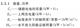

3. Thickness: 0.115 - 0.50 mm
4. Width: 600 - 1050 mm
5. Length: 600-1200mm
Tin Coating: ordinary 2.8 or 2.8g and 5.6g or 5.6g, we can produce according to customer's requests