3. Fixture structure and design points (1) Fixture structure Figure 2 is a schematic diagram of the structure of the key process vehicle fixture. The fixture is mainly composed of the clamp body 3, the floating support column 4, the springs 5 ​​and 8, the locking screws 6 and 10, the floating support nail 7, the central floating bearing 9, the pressing support column 12, the inverted cone inner hexagon head screw 13, the cylindrical positioning Pin 2 and chamfered pin 1 are composed. (2) Design points Due to the large production volume of parts, special tooling is set on the CNC lathe. The clamp pin 3 is provided with a cylindrical positioning pin 2 and a chamfered pin 1. When the workpiece 11 is mounted on the cylindrical positioning pin 2, the back side is Then, on the end faces of the three pressing support columns 12, the inverted cone inner hexagon head screws 13 are passed through the tapered holes which have been die-cast on the workpiece 11, and the workpiece 11 is clamped on the pressing support columns 12. However, the end face of the screw head must be lower than the machining plane of the workpiece 11, because the positioning surface of the workpiece 11 is short, and the clamping form of the pressing strut is used to obtain a good effect. In order to prevent vibration during machining, a floating support pin 7 is placed in contact with the workpiece 11 in the middle of the triangular string of the pressing support column 12, and then the locking screw 6 is tightened, and the center floating bearing 9 is also in contact with the workpiece 11. , and tighten the locking screw 10 to complete the clamping of the workpiece 11 before entering the machining program. 4. Selection of tools and cutting conditions (1) Choosing a tool suitable for the characteristics of the workpiece In order to meet the processing characteristics of the aluminum alloy, the rough car adopts the YD101 cemented carbide tool, and the refined car uses the polycrystalline diamond tool. The tool angle is 5°~20° for the rake angle, 4°~12° for the back angle, 30°~90° for the main declination, the small value of the roughing tool, and the large value of the finishing tool to play the rough finishing tool. Cutting function to ensure the stability of processing quality. (2) The choice of cutting amount The cutting force is closely related to the cutting amount. It is found in the test: After the feed amount is increased at the same time, the deformation of the workpiece is also increased due to the increase of the cutting force; When the feed rate is large, the cutting force is decreased, but the cutting residual area of ​​the machined surface is increased and the surface roughness value is increased. Therefore, when processing the aluminum alloy pump body, the amount of back-feeding knife used for finishing is ap = 0.08 ~ 0. 15mm, the feed amount f = 0. 1 ~ 0. 15mm / r, cutting speed vc = 60 ~ 120m/min. (3) The selection of the cutting fluid is based on the material of the workpiece and the tool and other factors. The emulsion is selected and the ratio of the concentration is higher. When mixing on site, use your finger to pry the cutting fluid that has been prepared. When the two fingers are in contact, the drawing can be produced. The so-called cutting fluid has strong penetrating power, which forms a lubricating film between the tool and the workpiece, reduces the friction and adhesion of the chip and the tool, and improves the surface processing quality of the part. 5. Programming skills When machining parts, the special functions of CNC lathes should be used reasonably to improve the machining accuracy of the parts. In order to obtain a consistent surface roughness for the end face machining of the part, the spindle speed is changed by calculating the position of the tool from the center of the workpiece by using the constant line speed function G96 command of the numerical control lathe, so that the instantaneous position of the workpiece and the cutting edge maintain a constant linear velocity relationship. In order to achieve a high level of quality of the entire processing surface. If deformation occurs during the turning of the part face, after the law is mastered, the two-axis linkage function of the CNC lathe can be used to compensate the taper to achieve the flatness requirement of the surface of the part. 6. Conclusion The tooling and cutting elements of the thin-walled part machining and the choice of cutting fluid are important foundations for the quality of the product. As long as the characteristics of the workpiece material, the process characteristics of the part clamping, the reasonable process steps and operation methods are established before the construction, and the factors affecting the deformation of the workpiece, the ripples and other quality problems in the process system are identified, and the correction is adjusted. Cutting parameters, while using the special functions of the CNC lathe, will surely achieve a high quality level of the machined surface. The quality of the machine tool fixture plays a decisive role in the quality of the part. According to the special shape of the part, the fixture is designed into a column structure such as positioning, support, compression and floating damping. Its rigidity can fully satisfy the product processing. The quality requirements, and the processing efficiency is relatively high. Previous page C&Z&U Purlin Roll Forming Machine Z Purlin Forming Machine,Z Channel Machine,C Shape Roll Forming Machine Wuxi Xinshijie Roll Forming Machinery Co., Ltd. , http://www.cn-rollformingmachine.com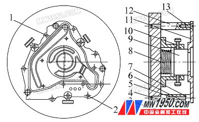
1. Chopped pin 2. Cylinder locating pin 3. Clamp specific 4. Floating support column 5, 8. Spring 6, 10. Locking screw 7. Floating support pin 9. Center floating support 11. Workpiece 12. Top pressure support column 13. Inverted taper cap screws