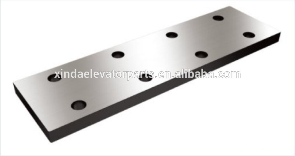
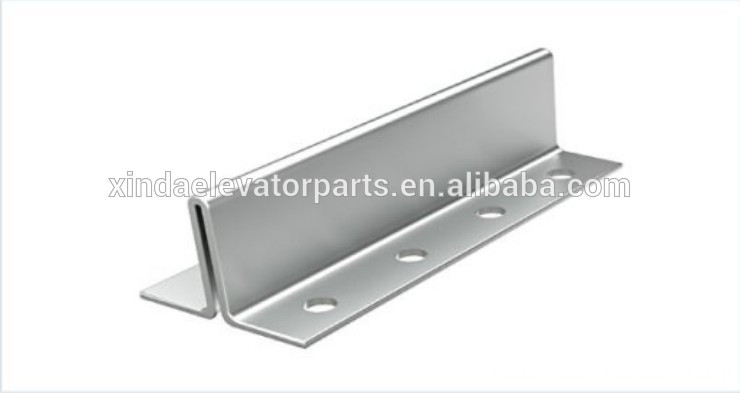
Elevator Machined Guide Rail, Elevator Hollow Guide Rail, Elevator Fish Plate for Guide Rail, Elevator Cold Drawn Guide Rail Ningbo Xinda Elevator Traction Technology Co., Ltd. , https://www.xinda-elevator.com
product
Specifications
Fluid sealing under high-temperature and high-pressure conditions has long been a challenging issue in engineering. Currently, the two primary types of sealing technologies are elastomeric seals and mechanical seals. While conventional engineering plastics and synthetic rubbers offer good sealing performance, they struggle to perform reliably in extreme heat. On the other hand, mechanical seals made from metal materials are highly resistant to high temperatures, making them more suitable for harsh environments.
This paper introduces a high-temperature-resistant mechanical seal designed for use in automotive exhaust auxiliary brake systems. The device is installed near the engine, where the exhaust gas temperature exceeds 700°C. Despite the severe operating conditions, the system has demonstrated effective braking performance in practical applications.
**Main Structure of the Mechanical Seal**
The mechanical seal structure is illustrated in Figure 1. The valve seat (5) is fixed to the exhaust manifold outlet using three screw holes, with the other end connected to the exhaust pipe flange. Figure 2 shows a detailed view of the sealing portion of the brake system.


**Brake Function Realization**
The vehicle's exhaust system includes the exhaust manifold, auxiliary brake, exhaust pipe, and muffler. Under high temperature and pressure, the rotating shaft is driven by a solenoid-controlled cylinder to open or close the butterfly valve plate, which is fixed by a force-transmitting fork. This controls the exhaust flow from the manifold, affecting the compression ratio on both ends of the engine piston. As a result, back pressure is created, slowing down the crankshaft via the connecting rod and consuming energy, thus achieving an auxiliary braking effect.
Due to its high-temperature resistance, the device can be directly mounted at the manifold outlet, close to the engine cylinder, allowing it to react quickly and in real time.
As shown in Figures 1 and 2, the rotating shaft (4) and sleeves (1, 6) have a certain movement gap. The outer circumference of sleeve 1 and the valve seat 5 are interference-fitted, forming blind holes, so no gas leakage should occur. However, the outer diameter of sleeve 6 and the valve seat 5 also have an interference fit, while the inner hole has a moving relationship with the rotating shaft, creating an unavoidable gap. This is the only path through which high-temperature and high-pressure exhaust gases can escape.
When the butterfly valve is closed (braking), some exhaust gas may leak, and when it is open (non-braking), even more may escape. In severe cases, whistling sounds can occur, degrading the surrounding environment. The movable washer rotates with the shaft, while the static washer and valve seat remain fixed, forming a cavity between them.
By reasonably selecting the number of gaskets and dividing them into multiple cavities, a step labyrinth path is formed, extending the gas escape route and increasing resistance along the path. Increasing the number of moving and static gaskets can also reduce the cavity volume, enhancing the throttling effect and increasing pressure loss. This helps meet the sealing requirements within engineering tolerances.
**Tolerance Matching**
During actual assembly, if the clearance between the moving washer’s inner hole and the shaft’s outer diameter, or between the static washer’s outer circle and the seat hole, is too large, axial turbulence may occur, causing the airflow to take a shortcut. If the fit is too tight, assembly becomes difficult, and excessive interference may deform the gasket, affecting cavity formation and rotating shaft movement, potentially leading to brake failure.
When choosing the appropriate material, it's essential to consider both high-temperature and normal-temperature states, as well as assembly processability.
The matching principle is as follows: first, minimize the axial gap between spacers; second, ensure radial micro-gap or no gap; third, keep the cavity formed by the components as small as possible.
In general, parts are made of stainless steel with similar axial thermal expansion properties. The axial clearance of the gasket is controlled at 0.05–0.10 mm, which has been experimentally proven feasible. Radial fitting options include K7/h6 (base shaft system), H7/K6 (base hole system), or a slight clearance fit H7/h6. These have been compared and verified. The difference lies in that transitional fits like K7/h6 and H7/K6 have a mating interference ratio of 42–45%, which improves sealing performance more than assembly ease. Meanwhile, the H7/h6 micro-clearance fit prioritizes assembly processability.
After determining the axial dimensions of the gasket, the selection of the outer diameter of the movable gasket and the inner diameter of the static gasket determines the cavity volume. Balancing the upper and lower cavity volumes enhances part interchangeability, which is beneficial for mass production and cost reduction.
Ensuring uniform axial gaps between dynamic and static gaskets is a critical assembly point, requiring special tooling to guarantee accuracy.
**Conclusion**
The high-temperature automotive exhaust auxiliary brake assembly has been successfully tested in the Jiangling N800 project and is now in mass production. A patent has also been applied for.